

1.
Select a location for each camera. When placing a camera, try to
follow as many of the following guidelines as possible.
•
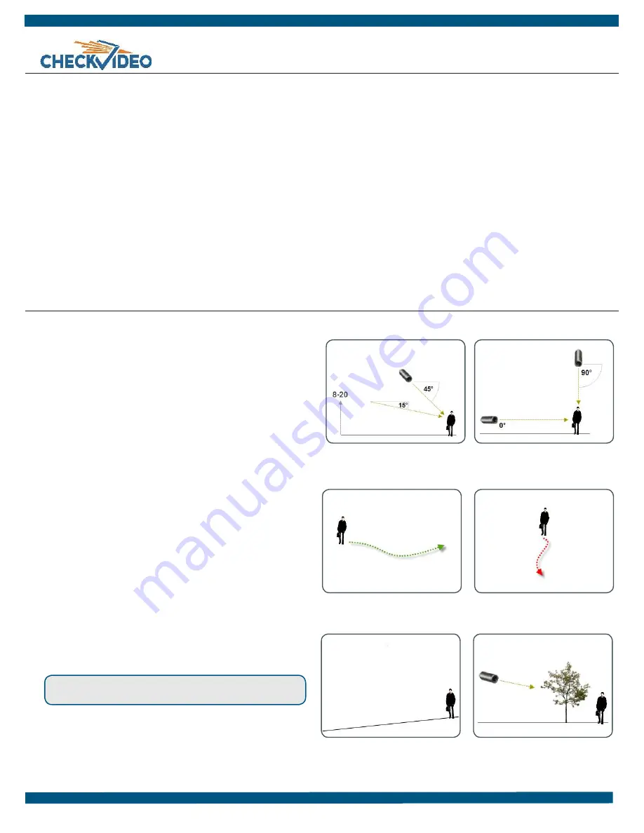
Camera Position:
Camera is mounted 8 to 20 feet above the
ground and tilts downward at an angle between 15° and 45°.
•
Target Direction of Motion:
People and vehicles (i.e.,
“targets”) should mostly travel from left-to-right or right-
to-left across the camera view, not directly toward or away
from the camera. Targets should remain in full view in the
detection zone of the camera view for at least the amount of
time specified in the event duration.
•
Vertical Orientation:
Objects in the camera view appear
upright (i.e., the camera body is not rotated clockwise or
counter-clockwise with respect to the ground plane).
•
Adequate, Even Lighting:
Lighting is constant and adequate for
the light requirement of your camera.
•
Cabling Issues:
Confirm that you can see live video from a
monitor connected to the Gateway prior to
connecting your cameras. Confirm that there is no video
split or horizontal bar caused by cable damage, crimping, or
extreme length.
•
Avoid Physical Obstructions or Distractions:
Where possible,
avoid physical obstructions and sources of constant motion
(e.g., moving doors).
•
Avoid Reflections, Glare, or other Extreme Lighting:
Where
possible, avoid reflective surfaces (e.g., mirrors, window
panes, water, or polished floors) or bright lights (e.g., headlight
glare, direct sunlight) directed at the camera.
Refer to the
CheckVideo Camera Placement Guide
, available
at
www.checkvideo.net
for more detail and examples.
2. Extend the cable from the camera location to your Gateway.
Before running cable, make sure that it is of sufficient length and
that the appropriate connectors are at each end.
3.
Make sure that all cameras have required video connections and
are powered up.
Equipment Requirements
•
CheckVideo Gateway
•
CheckVideo Gateway power supply:
9-12V DC, min 1.4 amp
•
Fixed, analog NTSC/PAL cameras (not included)
•
Ethernet cable to connect the CheckVideo Gateway to the
network
•
Computer or laptop with broadband access (customer provided)
(Optional:)
•
8 pin Phoenix connector for digital input/output contacts
•
Monitor for viewing live video during camera setup. This can be a
TV connected to a CheckVideo Gateway monitor connector with
a BNC to RCA cable.
•
UPS power supply
Before you begin, confirm that you have the necessary equipment and are in-
stalling your CheckVideo® Gateway on a network that meets minimum network
and equipment requirements. If this CheckVideo device will be monitored by a
central station, please contact the central station for a username and password
on their existing CheckVideo account. The central station will add the device to
their account.
If this device will be self-monitored, you will be creating a CheckVideo account in
Step Four.
Network Requirements
•
Active broadband Internet connection with an upload speed of at least 512
kbps
•
If you have an active firewall, it cannot block outbound traffic on ports 123
(used for network timing), 80 (HTTP), or 443 (HTTPS)
•
DHCP enabled
•
Access to your router configuration may be necessary
Step One
Check Equipment and Network
Step Two
Install Cameras
MORE EFFECTIVE
- Cameras are at a
15 to 45 degree downward tilt and
are mounted 8 to 20 feet high
LESS EFFECTIVE
- Cameras are
directly overhead (90 degrees) or
parallel to (0 degrees) the target
MORE EFFECTIVE
- A target traveling
from left to right
LESS EFFECTIVE
- A target traveling
directly toward the camera
CheckVideo Gateway for Broadband Networks
Installation Quick Reference
LESS EFFECTIVE
- Target not upright
(vertical orientation); camera body is
rotated 5 degrees or more
LESS EFFECTIVE
- Physical obstructions
between the camera and the target
,


