background image

Rev. 1/9/20 


Installation, Operation & Maintenance Manual 

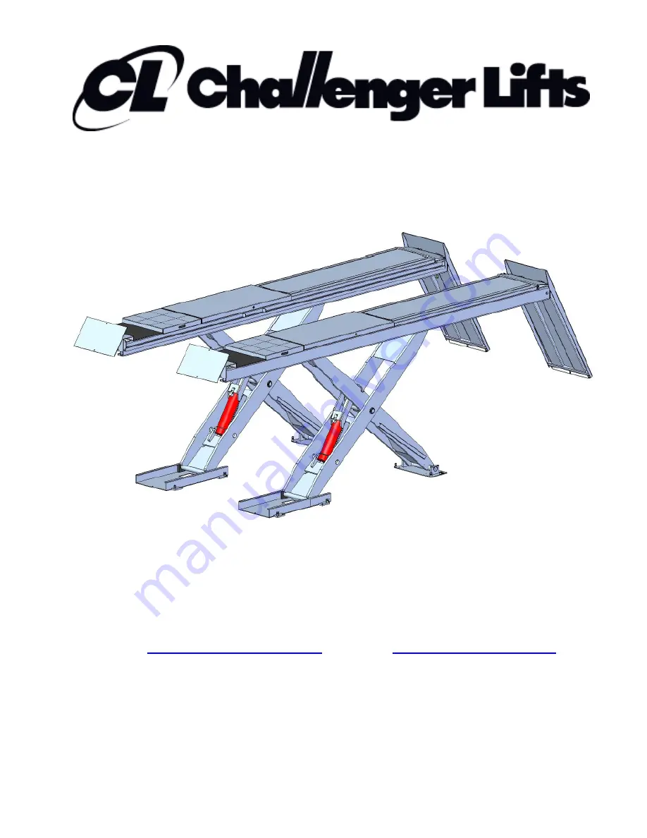
Scissor Alignment Lift 


Model SX14 & SX14R 

14,000 lbs. Capacity 

7,000

 LBS

.

 PER 

R

UNWAY


2311 South Park Rd Louisville, Kentucky 40219 

Email:

[email protected]

 Web site:

www.challengerlifts.com


Office: 800-648-5438 / 502-625-0700     Fax: 502-587-1933 


IMPORTANT:

  READ THIS MANUAL COMPLETELY BEFORE


INSTALLING or OPERATING LIFT


Summary of Contents for SX14

Page 1: ...14 SX14R 14 000 lbs Capacity 7 000 LBS PER RUNWAY 2311 South Park Rd Louisville Kentucky 40219 Email sales challengerlifts com Web site www challengerlifts com Office 800 648 5438 502 625 0700 Fax 502...

Page 2: ...t must be used and utmost attention applied DANGER OF FALLING Indicates that during installation the operator crosses zones where there is high risk of falling always be particularly careful IMPORTANT...

Page 3: ...eel Alignment 176 I Min 4 Wheel Alignment 70 J Distance to Controls Width 24 min 64 max K Distance to Controls Length 40 min 74 max Minimum Recommended Bay Size 14 x 28 Lift Shipping Dimensions Weight...

Page 4: ...4 LIFT BASE LAYOUT Fig 2 Base Layout PIT LAYOUT Fig 3 Pit Details...

Page 5: ...4 2 Hydraulic Cylinder X X 5 2 Recess X X 6 2 Oscillating Plates X X 7 2 Front Stop X X 8 2 Access Ramps X 9 1 Control Console X X 10 3 1 1 Protective Pipe Ducts X 11 2 Union Platform X 12 1 Hardware...

Page 6: ...olling jack raised NEVER remove the wheel stop or the pivoting entrance ramp union They prevent the vehicle from coming off the platform NEVER lift vehicles using equipment other than that approved by...

Page 7: ...rer WHEEL STOP DEVICES Wheel stop and entrance ramp union Front and rear of both lift platforms Prevents the vehicle from coming off the platforms SIGNALS Labels and Decals See paragraph Labels and Sa...

Page 8: ...RISK OF ELECTRIC SHOCK 3 RISK OF EXPLOSION 4 FUSE 12 ALI GOLD LABEL 14 NOTICE 16 CAUTION WARNING SAFETY INSTRUCTIONS 17 EARTH CONNECTION 22 MAX CAPACITY 23 DO NOT STAY NEAR THE LIFT IN MOVEMENT 25 PI...

Page 9: ...9...

Page 10: ...10 CONTROL UNIT 34 5 16 3 17 4 2 28 14 12 27 26 26 29 31 30 35...

Page 11: ...11 LABEL 2 LABEL 2A LABEL 3 LABEL 3A LABEL 4 LABEL 4A LABEL 5 LABEL 5A...

Page 12: ...12 LABEL 12 LABEL 14 LABEL 14A LABEL 16 LABEL 17...

Page 13: ...13 LABEL 22 LABEL 23 LABEL 25 LABEL 26 LABEL 27 LABEL 28 CHALLENGER SERIAL TAG LABEL 29...

Page 14: ...14 LABEL 30 LABEL 31 LABEL 34 LABEL 35 LABEL 35A...

Page 15: ...ses for 3 4 seconds to clear the mechanical locks b The lift begins lowering PO PHOTOCELL OVERRIDE If there is a difference in height of more than 50 mm power to the motor will be cutoff Use the PO bu...

Page 16: ...ft Be sure that all safety decals have been attached to the control console of the lift Verify that all authorized operators know the location of these decals and fully understand their meaning Replac...

Page 17: ...ame piping and forms conform to details shown in Fig 3 Pit frame and temporary pit forms are NOT PROVIDED and will be the responsibility of the installer Total pipe chase length should not exceed 13 f...

Page 18: ...onnect the hydraulic lines to the block connections inside the control unit Fig 6 NOTE The hydraulic lines from the lift platforms can connect to either port Fig 6 Hydraulic Connections PNEUMATIC CONN...

Page 19: ...g 9 F If platforms lower into a lock position press UP for 5 seconds G Bleed cylinders until oil begins to escape H Press UP until both platforms stop moving I CLOSE all 3 valves J Press PHOTOCELL OVE...

Page 20: ...vel of the platforms at the fully lowered position Each platform should contact 6 bolts when lowered Tighten lock nuts when done 8 Adjust rear runway bolt to make contact with floor when lift is compl...

Page 21: ...the employer shall insure that the lift maintenance personnel are qualified and that they are adequately trained in the maintenance of the lift The Owner Employer shall maintain the periodic inspectio...

Page 22: ...22 AIR SWITCH BASE SETTING...

Page 23: ...lace an object below reflector and move upwards check when the YELLOW LED is switched off mark the position the work field is between the two marks adjust photocell so work field is centered on Reflec...

Page 24: ...rming any operation near or on moving mechanical parts or before performing any operation on powered parts of the system Use Lock Out Tag Out procedures to lock the cut off switch in the open position...

Page 25: ...ection checklist and maintenance log sheet Replace all Safety Warning or Caution Labels if missing or damaged See page 8 WHAT WHERE MACHINE STATUS HOW USE Daily SYNCHRONIZATION PLATFORMS IN MOTION VIS...

Page 26: ...26 LUBRICATION POINTS repeat symmetrically on both sides of the lift...

Page 27: ...Prevent spills Wash frequently without using aggressive cleansers Do not dry hands with rags soiled with oil Change any clothing that is dirty or greasy and always change clothes at the end of the wo...

Page 28: ...are no longer engaged Activate Lock Release using the dedicated manual valve on solenoid valve EV2 turn screw 90 ENSURE THAT MECHANICAL LOCKS ARE OPEN Activate solenoid valve EV1 see photograph A or B...

Page 29: ...pickup tube broken a 4 clamping screws loose a 5 oil leakage a 6 check the pressure value b 1 lowering valve stuck open c 1 limit valve broken d 1 Check that the motor turns in the direction shown by...

Page 30: ...30 Fig 13 Electrical Wiring Diagram Console Lid Switches...

Page 31: ...31 Fig 13 Electrical Wiring Diagram Continued...

Page 32: ...32 Fig 14 Hydraulic Diagram...

Page 33: ...33 Fig 15 Pneumatic Diagram...

Page 34: ...34 PARTS BREAKDOWN 11 16 10 12 10 9 7 8 6 5 2 1 4 3 13 12 15 14...

Page 35: ...ion 1 1361030010 1 Transformer 2 1451380000 1 Fuse 3 1501770000 1 Contactor 4 1501710100 1 1ph 2 3ph Magnetothermic Switch 5 1371080000 1 Main Switch 6 1422070131 1422070132 1422070133 1422070135 4 Te...

Page 36: ...36 7 12 14 5 3 4 16 6 10 9 11 15 8 17 17 13 18 2 19 20 21 1 350 BAR 110 BAR...

Page 37: ...8mm O D 13 1201967307 2 Hydraulic Hose Straight Fittings 14 1201470507 1 Main Supply Hose 15 1164120008 3 Tee Fitting 16 1161030010 2 6JIC x BSPP Straight Fitting 17 1265080009 2 Push Lock Elbow 18 1...

Page 38: ...38 1 4 5 9 11 12 18 15 13 20 23 22 21 24 6 2 14 25 16 26 3 8 3 7 10...

Page 39: ...e 15 DX77 54 2 6mm x 4mm Push Lock Reducer 16 1291020008 2 6mm Tube 14M Long 18 1291060008 2 4mm Tube 8M Long 19 1262090110 2 6mm Push Lock Y Union NOT SHOWN 20 1263040009 1 Tee Fitting FNPT 21 126504...

Page 40: ...40 26 42 24 44 43 47 48 49 50 25 42 43 27 28 30 31 32 29...

Page 41: ...x Bolt 44 1012080300 4 M8 x 30 Flat Head Screw 45 1061040000 2 M4 Flat Washer 46 1011040100 2 M4 x 10 Pan Head Screw 47 30501 3 Straight Hose Cover 48 30503 1 1 Angled Hose Cover Left 49 30503 2 1 Ang...

Page 42: ...42...

Page 43: ...55076 4 Bushing 13 3036055730 2 Lock Release Cylinder 14 3036058306 4 Bushing 30 1141490000 2 Bushing 32 1071450003 4 45mm Snap Ring 33 1012100300 2 M10 x 30 FHSCS 34 1023080200 8 M8 x 20 Cone Point S...

Page 44: ...44 29 48 47 21...

Page 45: ...8 VS10 31 08 4 M8 x 12 Flat Head Screw 39 X10 095 2 M16 Hex Nut 40 1003160700 2 M16 x 70 Hex Bolt 41 MR6 002 4 M10 x 20 Hex Bolt 47 1056080000 4 M8 Lock Nut Optional 48 Q4P09 006 4 M8 x 20 SHCS Option...

Page 46: ...0 2 Greasing nipple 15 1141050000 2 Greasing nipple Replace all worn damaged or broken parts with parts approved by Challenger Lifts Inc or with parts meeting Challenger Lifts Inc specifications Conta...

Reviews: