background image

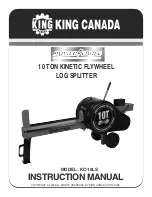
30 ton log splitter

Model

96907

set up And operAting instructions

Diagrams within this manual may not be drawn proportionally.

Due to continuing improvements, actual product may differ slightly from the product described herein.

distributed exclusively by Harbor Freight tools

®

.

3491 Mission Oaks Blvd., Camarillo, CA 93011

Visit our website at: http://www.harborfreight.com

 read this material before using this product.  

Failure to do so can result in serious injury. 

sAVe tHis MAnuAl.

Copyright

©

 2007 by Harbor Freight Tools

®

.  All rights reserved.  No portion of this 

manual or any artwork contained herein may be reproduced in any shape or form 

without the express written consent of Harbor Freight Tools.

For technical questions or replacement parts, please call 1-800-444-3353.

Summary of Contents for 96907

Page 1: ...ission Oaks Blvd Camarillo CA 93011 Visit our website at http www harborfreight com Read this material before using this product Failure to do so can result in serious injury Save this manual Copyrigh...

Page 2: ...tter Assembly 8 Filling the Hydraulic Fluid 11 Operating Instructions 12 Work piece set up 12 General operating instructions 12 Transporting the Log Splitter 13 Maintenance And Servicing 15 Cleaning m...

Page 3: ...the safety alert symbol It is used to alert you to potential personal injury hazards Obey all safety messages that follow this symbol to avoid possible injury or death DANGER indicates a hazardous sit...

Page 4: ...afety Stay alert watch what you are doing and use common sense when operating the Log Splitter Do not use the Log Splitter while you are tired or under the influence of drugs alcohol or medication A m...

Page 5: ...the equipment s operation If damaged have the Log Splitter repaired before use Many accidents are caused by poorly maintained equipment Keep cutting tools sharp and clean Properly maintained cutting t...

Page 6: ...es in the work area and in the surrounding area Never place your hands or body near a hydraulic fluid leak Never check for a leak with your hands or other body parts High pressure fluid can be forced...

Page 7: ...cover of this manual as soon as possible Set Up Instructions Read the entire Important Safety Information section at the beginning of this manual including all text under subheadings therein before se...

Page 8: ...t the bearing Back off the Spindle Nut one half turn Insert a Cotter Pin 53 through both the Axle and the Spindle Nut and bend the end of the Pin back to hold it in place Log Splitter Assembly Please...

Page 9: ...the directional Arrows on the unit they will aid in assembling the unit in the proper orientation Use Hex Bolt 43 to install the support assembly as shown in Figure A left Figure A The Push Pin 42 is...

Page 10: ...ase call 1 800 444 3353 Figure B The control valve stand is attached onto the oil reservoir with 4 Hex Bolts 70 as shown in Figure B Figure C The Spindles are used to assemble and connect the Log Lift...

Page 11: ...onnected to the Hydraulic Oil Cap wipe it clean then dip it back in to check the level The oil should be at the upper notch of the Dipstick Be sure that the hydraulic oil level is between 4 5 and 8 ga...

Page 12: ...manufacturer owner s manual thoroughly before starting this engine or using this product This product requires engine oil hydraulic oil and fuel to be added before starting Attempting to start the en...

Page 13: ...e lever back to withdraw the Ram Continue loading logs on the Log Lift and splitting them until the job is done To prevent accidents turn the engine off after use Clean then store the tool in a dry ar...

Page 14: ...60 for the Wheels before traveling Do not drive faster than 55 MPH when the Log Splitter is connected to the vehicle Before transporting and at 500 mile intervals during every trip check and tighten t...

Page 15: ...ter every use wipe down the Log Splitter to remove any tree sap or dirt This will extend the life of the unit Always keep the wedge and base clean Clean and then grease the moving parts of this machin...

Page 16: ...st and assembly diagram in this manual as a reference tool only Neither the manufacturer or distributor makes any representation or warranty of any kind to the buyer that he or she is qualified to mak...

Page 17: ...4 12 31 Hydraulic Fitting 3 8 2 32 Hex Nut M14 5 33 Spindle 3 M12 2 34 Cylinder 2 1 35 Hex Bolt M10x90 1 36 Washer 10 9 37 Hex Bolt M10x30 6 38 Hex Nut M12 1 Part Description Qty 39 Hitch Coupler 1 40...

Page 18: ...Page 18 SKU 96907 For technical questions please call 1 800 444 3353 Assembly diagram...

Page 19: ...ring Seal 38 5 3 55 1 01 9 J Type Rubber Seal 50 70 10 1 01 10 Y Type Seal 50 70 10 1 01 11 O ring Seal 50 3 55 1 01 14 Nylon Washer 127 118 2 3 Part Description Qty 31 5 Nylon Cap 63 54 2 2 2 31 6 N...

Page 20: ...anty is expressly in lieu of all other warranties express or implied including the warranties of merchantability and fitness To take advantage of this warranty the product or part must be returned to...

Reviews: