Celestron 10110, Instruction Manual
Looking for the Celestron 10110 user manual? Look no further! Download your free Instruction Manual from manualshive.com to learn all about this fantastic product. Get all the information you need to maximize your experience with the Celestron 10110 telescope.
Share
Download


Reviews:
No comments
Related manuals for 10110
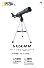
NG50MM
Brand: National Geographic Pages: 12

Europa 114
Brand: Orion Optics Pages: 16

9828
Brand: Orion Pages: 8

FOA-60
Brand: Takahashi Pages: 24

Micro Guide
Brand: Celestron Pages: 12

Inspire 100AZ
Brand: Celestron Pages: 40

ALT-AZ Series
Brand: AmScope Pages: 16

ZenithStar 110
Brand: William Optics Pages: 9

709AZ3
Brand: SKY-WATCHER Pages: 9


