Caviblaster 1325-D, Operation & Maintenance Manual
The Caviblaster 1325-D Operation & Maintenance Manual is an essential companion to effectively operate and maintain your Caviblaster 1325-D equipment. This comprehensive manual provides step-by-step instructions and safety guidelines, ensuring optimal performance and longevity of your device. Download this manual for free from our website, manualshive.com, today!
Share
Download


Reviews:
No comments
Related manuals for 1325-D

KH 2243
Brand: E-Bench Pages: 37

UEYPOPL/12-4Q/3D
Brand: Cristec Pages: 54

SDV17-SQ
Brand: NextBase Pages: 52

FGHi3500
Brand: Feider Machines Pages: 26

Hard Gear SGE3500BSi
Brand: DAISHIN Pages: 28

ElectroMate VEC097
Brand: Vector Pages: 20

LGS170
Brand: OWI Pages: 1

CMXGGAS030731
Brand: Craftsman Pages: 40

919.679580
Brand: Craftsman Pages: 36

919.679501
Brand: Craftsman Pages: 28

CMXGGAS030733
Brand: Craftsman Pages: 40

CMXGIAC2200
Brand: Craftsman Pages: 60

CMXGGAS030730
Brand: Craftsman Pages: 36

580.675511
Brand: Craftsman Pages: 60
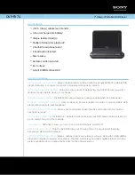
DVP-FX74
Brand: Sony Pages: 2

DVP-FX1021 - Portable Dvd Player
Brand: Sony Pages: 2

DVP-FX74
Brand: Sony Pages: 36

DVP-FX740DT
Brand: Sony Pages: 188


