BACC-KEYPAD-
DC-U
Instruction
Manual
ENGLISH
Read carefully the instruction man-
ual.
If the instrument is used in a
manner not specified by the produc-
er, the protection provided by the
instrument may be impaired.
Maintenance:
make sure that the connections are correctly
carried out in order to avoid any malfunctioning
or damage to the instrument. To keep the
instrument clean, use a slightly damp cloth; do
not use any abrasives or solvents. We recom-
mend to disconnect the instrument before
cleaning it.
n
SUPPLY SPECIFICATIONS
Power supply
9-17 V DC.
Current consump-
tion
Max. 100 mA.
n
DUPLINE
®
SPECIFICATIONS
Voltage
8.2 V.
Maximum Dupline
®
voltage
10
V.
Minimum Dupline
®
voltage
4.5 V.
Maximum Dupline
®
current
2 mA.
n
GENERAL SPECIFICATIONS
Address assignments/channel program-
ming
If it is used with the SH2WEB24 the
address assignment is automatic: the controller
recognises the module through the SIN
(Specific Identification Number) that has to be
inserted in the SH tool. If it used with the BH8-
CTRLX-230 the channels are fixed, cannot be
altered, see channel table.
Indications
3 LEDs,
one yellow and two dual colour red/green
LEDs. The behaviour of the three LEDs is user
configurable. Built-in buzzer.
Degree of pro-
tection
IP 67.
Operating temperature
-15° to
60°C (+5° to 140°F).
Storage temperature
-
30° to 80°C (-22° to 176°F).
Humidity
(non-
condensing) 100%.
Number of wires
4-wire
cable, 8 m length.
Approvals
CE.
n
MODE OF OPERATION
BACC-KEYPAD-DC-U is a flexible keypad for
applications in very different fields: when it is
working properly the yellow LED is lit (the left
one). If the keypad is activated typing a con-
firmed code (code followed by #, e.g. 1234#),
the yellow and the green LEDs are lit for the
activation time and the buzzer replies with two
short beeps. If the code is not confirmed, the
red LED is lit shortly and the buzzer replies with
a short and a long beep. Additionally the
buzzer, the green and the red LEDs can be acti-
vated directly by programming them with the
configuration software. If 4 wrong codes are
typed in a row, the keypad will be blocked for 1
minute (red LED flashing). After this minute,
new attempts can be made. The access codes
are stored in the memory positions from 1 to 28.
The pre-programmed code is 1234 for pos 1.
Codes can be programmed/changed or delet-
ed by using the MasterCode (MC): the MC is by
default 4711.
Codes – overview - BACC-KEYPAD-DC-U
The codes may contain numbers from 0-9 and
they can be any length up to 8 digits.
SIN 255.255.255/999.999
SIN 255.255.255/999.999
MANUAL BACC-KEYPAD-DC-U V2 code 15-029-594 / 270314
http://www.carlogavazzi.com/
CARLO GAVAZZI
Programming the user codes
1) Key in the
MC and # (green LED is lit). 2) Key in the pos nr
and # (from 1 to 28, yellow and green LEDs are
lit). 3) Key in the code and # (from 1 to 8 digits).
For more codes repeat from step 2. Exit pro-
gramming mode by pressing #. You may also
wait 10 seconds which is the time-out period
that
exits
programming.
Example:
4711#2#345678# followed by #. The code
345678 is now active, placed in pos 2.
Changing a code
Follow the above – just over-
write the code. Example: 4711#2#897# fol-
lowed by #. The code 897 is now active, placed
in pos 2. The old code is deleted (overwritten).
Deleting a code
Follow the above. In step 3
just press # - then the key is deleted. Example:
4711 # 2 # #. The code in place 2 is now deleted.
Delete all codes
Key in the MC# 2500# - all
user codes in positions 1-28 are then deleted.
Example: 4711# 2500#. All user codes are now
deleted.
Exit the programming mode
Timeout
is 10 sec. Programming mode will automatical-
ly exit 10 sec after the last key is pressed.
Alternatively press #.
Advanced options in the
BACC-KEYPAD-DC-U Keypad
The advanced
options are stored in a second memory area
from location 01 to location 06. These memory
locations are accessed by using the Service
Code (SC). These locations contain the config-
uration setup, and should only be altered by a
skilled installer. The default values are:
Servicecode (SC)
12347890, placed in loca-
tion 01.
Mastercode (MC)
4711, placed in
location 00.
Short overview
The MC is for pro-
gramming/deleting/changing the user codes.
MC gives access to the normal memory posi-
tions 1-28, where the user code is placed. SC
gives additional access to the extended mem-
ory locations 01 to 06, in order to configure the
keypad.
As default (can be modified – see
explanation 4 below), the entering of the SC
must be done within a time-out of 10 sec-
onds after power-on. After having used the
SC once, you may continue modifying con-
figurations until the last # is pressed, or
time-out expires.
Example
You want to change both the SC and
the MC. Apply power to the keypad. Within 10
seconds, type the SC and modify the SC as
described in the examples below. The green
LED is still lit. Modify the MC as described in
the examples below. Now the keypad has new
SC and MC. Press #, this exits the program-
ming mode (or wait 10 seconds).
Reset
Power
ON, SC # 0250 # - The keypad is set back to
factory default.
Examples
(Assuming the SC is 12347890).
Example 1
Changing the MC to 47889: Power
ON, 12347890#00#47889##.
Example 2
Changing the SC to 151618: Power ON,
12347890#01#151618#151618##.
Example 3
Reset the keypad to factory defaults: Power
ON, 12347890#0250##.
Example 4
Changing
the MC (mastercode) to 5643, and the SC (ser-
vicecode)
to
1357:
Power
ON,
12347890#00#5643#01#1357#1357##.
See the function codes in the table
“Configuration of the Keypad”.
1) Explanation to table location 02. LED indi-
cation
(default = 31) There are three LEDs on
the keypad, a yellow and two dual colour LEDs,
where red is used for the middle one and green
for the one to the right. From default, the yellow
LED is lit when NORMAL mode is active (when
power is applied, and no keys are pressed).
When a key is pressed, the yellow LED blinks
(switches off momentarily), and the buzzer
beeps. ACTIVE mode is the state when the key-
pad gives a response, e.g. when the correct
code is entered. By choosing other values in
the memory location 02, other LED combina-
tions can be achieved. The nn (table) and the
LED indication for NORMAL and ACTIVE
(approved code) is as follows:
To achieve the wanted LED combinations, just
add together the values in the table above, and
insert this sum in location 02.
Example 1
NOR-
MAL yellow and ACTIVE yellow and green.
Values from the table, 01 + 10 + 20. Default in
location 02=31 (Add 01+10+20). (01= yellow
LED in NORMAL condition); (10= yellow LED in
ACTIVE condition); (20= green LED in ACTIVE
condition). Entering the value into the keypad:
power OFF, power ON, type SC#02#31##.
Example 2
NORMAL green and ACTIVE red.
Values from the table, 02 + 40 = 42. Entering
the value into the keypad: power OFF, power
ON, type SC# 02# 42##.
Example 3
NORMAL
nothing and ACTIVE yellow. Values from the
table, 00 + 10 = 10. Entering the value into the
keypad: power OFF, power ON, type
SC#02#10##.
2) Explanation to location 03.
Time duration of output address B3
(Default
= 3 seconds) When the bell button (
) is
pressed and released, the output address B3 is
active for a time period defined in location 03.
Changing the value gives other time values
from 1 to 99 seconds. If the value written is 00,
the button acts as a toggle switch; first time
pressed, B3 is ON, next time pressed B3 is
OFF. Examples: (see * above for entering the
SC). Output active for 7 seconds: SC#03#07##.
Output acting as a toggle switch: SC#03#00##.
3) Explanation to location 04. Duration of
address B4 output time
(Default = 5 seconds)
When a correct entry code is typed, the B4 is
active for a time period defined in location 04.
This time period can be altered from 1 to 100
seconds, or from 1 to 99 minutes. Entering a
value from 1 to 100 results in delays between 1
and 100 seconds. Entering a value between
101 and 199 results in delays between 1 and 99
minutes. Entering 0 results in toggle switching.
Examples
You want an output that is active for
3 seconds: SC#04#3##. You want an output
that is active for 15 minutes: SC#04#115##.
Use default value for smart-house applica-
tions. 4) Explanation to location 05. Buzzer,
toggle, SC, output B4
Default 05=00: Buzzer
on and all other in off mode.
To achieve numerical value, just add the values
in the table. E.g. buzzer on, toggle mode and
output (B4) inverted, just add 0, 2 and 8 (=10).
Buzzer
The internal buzzer makes a sound in
different situations when the address is OFF.
When this address is ON, the buzzer is silent in
all situations.
Toggle mode
The output (B4) is
normally OFF. When the accepted code is
entered, the output goes on for the time period
defined in location 03. If toggle mode is set to
‘ON’, any codes selected with 8-digit numbers
will set the output B4 ‘ON’ until next time a
code is accepted. All other codes will give a
timed output. In smart-house applications, set
this value to ‘OFF’.
SC: Power ON/OFF func-
tion
If this is set to ‘ON’, the SC can be entered
without having the need of powering off the
keypad. If set to ‘OFF’, the keypad must be
powered OFF before the SC is entered.
Output
(B4) inverted
By default, the output is normal-
ly OFF. When a code is accepted, the output
will switch ON for a time period, and back OFF
again when the time expires. (Set in location
04). If wanted, the output can be inverted by
adding the value ‘8’ to the location 05. In
smart-house applications, leave this value as
‘normally OFF’!
Examples
Buzzer ON, toggle
mode ON and output inverted is wanted:
Buzzer=0, toggle=2 and inverted output =8.
Write the sum (0+2+8=10) in location 05
SC#05#10##. For smart-house use, buzzer is
ON, and the possibility to change SC without
powering off the keypad is wanted: Buzzer=0
and SC=4. Write the sum (0+4=4) in location
05: SC#05#04##.
5) Explanation to pos 06.
Programming of the behaviour of the out-
puts B3 and B4
Default 04 = 29 The two out-
puts act in the following two manners: 1) By
default, the output B4 is activated whenever a
code is accepted. It does not matter in which
position the code is placed. Example: the
entrance codes for three family members are
placed in locations 02, 03 and 04. A housemaid
has a code placed in position 05. All codes
accepted will activate address B4 for a time
period. 2) By default, the bell key (
), when
pressed, will activate output B3 for the time
period set in location 03. A value between 1
and 28 can be placed in location 06.
Depending of the value, one of the two
addresses (B3 or B4) will activate, according to
the code’s position in the code list. Let us
assume that you have codes placed in position
01, 02, 03, 07, 14 and 21 of the code list.
Normally, all these codes will activate address
B4. The address B3 will give an output when
the bell key is pressed. You want, for some rea-
son, to differ between the persons accessing
the building.
Solution
Select two areas in the
user codes, and put the codes for the users
who have access to one part of the building in
one half of the code area, and the other codes
for the users in the other code area. Then select
the ‘diversion line’ in the code list by entering
the wanted number in the location 06. In the
above example, if the number selected is 12,
the codes below position 12 will activate
address B4, and the codes from position 12
and up will activate address B3. The keypad
will differ the two entries by sounds: 2 short
beeps for the ‘low’ positions, and 1 short beep
for the ‘high’ positions. Example The house-
maid is not allowed to access the basement.
Therefore the zone alarm is active in the base-
ment. When any of the three members of the
family enters the house, the alarm for the whole
house is disarmed. When the housemaid enters
her code, the alarm for the basement zone is
still active.
How to achieve this
The house-
maid’s code is placed as a code in second part
of codes entered, e.g. in pos. 19. As you have
28 places for codes all in all (as shown in the
table ‘Codes – overview’), you can select that
e.g. the last 10 places give access to the whole
house, except for the basement. The codes
from position 1 to 18 (low) will arm and disarm
the full alarm system. The codes placed from
position 19 to 28 (high) will disarm the alarm,
but the zone alarm for the basement is still
active.
Configuring the keypad for this exam-
ple
Write the value 18 in location 06:
SC#06#18## This will activate output B4 for
codes placed in position 1-18, and output B3
for codes placed in position 19-28.
Attach here the label
Write here the location
Pos Code
Name
Pos Code
Name
1
1234
15
2
16
3
17
4
18
5
19
6
20
7
21
8
22
9
23
10
24
11
25
12
26
13
27
14
28
Wire Colour
Keypad –
Inst
Function
Description
Red
+ 12 V DC
Supply, 9-17 V/ max.
40 mA
Black
0 V, GND
Supply negative
Yellow
D +
Dupline
®
bus positive
Blue
D -
Dupline
®
bus negative
Address Function
B3
Active for a time period after the ‘
’
key is released
B4
Active for a time period when cor-
rect code is entered
B5
Address of red LED
B6
Address of green LED
B7
Address of buzzer
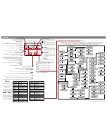
Configuration of the Keypad:
Overview and options by the SC (servicecode)
Programming
Key in SC followed by # etc.
Location
Factory
default
Function
Description
Programming
New value
00
4711
Mastercode (MC)
00#
nnnnnnnn#
01
12347890 Servicecode (SC)
01#
nnnnnnnn#
nnnnnnnn#
(must be typed
twice)
02 see
1
31
LED settings
Yellow in normal mode,
Yellow and green when
code is OK
02#
nn #
03 see
2
3
Output time for
address B3
Address B3 time for
‘
’ (bell) key
03#
0=toggle, n in
sec
04 see
3
5
Output time for
address B4
Code valid output
address B4
04#
0=toggle, n in
sec/min
05 see
4
0
Setting of
functions
Variables for buzzer,
toggle, SC and
output
05#
nnn #
06 see
5
29
Activation of out-
put for user codes
Output for bell (29),
codes >xx
06#
nn#
Value in nn Yellow LED Green LED Red LED
NORMAL
01
02
04
ACTIVE
10
20
40
Value of NN
ON
OFF
Buzzer
0
1
Toggle mode, (for 8 digit codes)
2
0
SC: Power on/off function
4
0
Output (B4) inverted
8
0
Installing your new BACC-KEYPAD-DC-U
keypad
BACC-KEYPAD-DC-U connected to the
BH8-CTRLX-230
Addresses used by the keypad
(Fixed
addresses, cannot be altered).
MANUAL BACC-KEYPAD-DC-U V2 code 15-029-594_MANUAL BACC-KEYPAD-DC-U V2 code 15-029-594.qxd 28/03/14 14.39 Pagina 1