background image


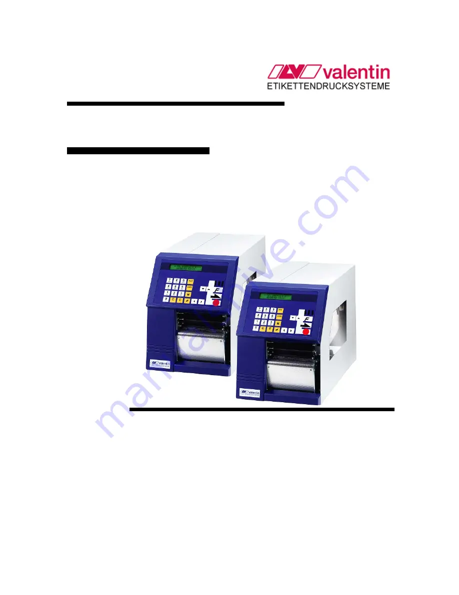
Service Manual - English 


Vario II Series 


79.55.023   •   September 2002 


All rights reserved. 


Carl Valentin GmbH   •   Neckarstraße 78 – 82 & 94   •   78056 Villingen-Schwenningen 
[email protected]   •   www.valentin-carl.de 

Summary of Contents for Vario II series

Page 1: ...Service Manual English Vario II Series 79 55 023 September 2002 All rights reserved Carl Valentin GmbH Neckarstraße 78 82 94 78056 Villingen Schwenningen support valentin carl de www valentin carl de ...

Page 2: ......

Page 3: ...ARD SLOT OPTION 5 Plan of components 5 Components and plug in positions 6 INPUT OUTPUT PLATE OPTION 7 Plan of components 7 Jumper plan 8 Components and plug in positions 8 ETHERNET OPTION 9 Plan of components 9 Components and plug in positions 9 CONNECTIONS BACK PANEL 10 MEASURING POINTS POWER UNIT 11 Voltage supply 11 Printhead voltage 12 Printhead voltage 12 Tranformer voltage 12 Feed motor 13 M...

Page 4: ...0 EXCHANGE OF DEFECTIVE COMPONENTS 21 Exchange of fuse 21 CPU 23 Printhead FPGA 24 Input Output FPGA 24 Batterie 24 Power unit 25 OPTIONS 26 Refit memory card slot 26 Refint input output plate 27 Refit RS 485 and RS 422 plate 30 Refit Ethernet plate 31 Refit dispenser 32 Refit cutter 33 Adjust cutter ledge 35 MECHANIC 37 Exchange of printhead 37 Adjustment of printhead Flat Type KF 38 Adjust rewin...

Page 5: ...Table of contents 3 CONNECTION PLAN INTERFACES 45 Centronics 45 RS 232 45 RS 485 and RS 422 46 Ethernet Option 47 INDEX 49 ...

Page 6: ......

Page 7: ...Service Manual 1 WIRING PLANS Electronics ...

Page 8: ...Service Manual 2 CPU Plan of components ...

Page 9: ...processor U5 U6 DRAM U8 RESET component U10 RTC U11 INPUT OUTPUT FPGA U13 RS 232 component U14 USB component U20 Printhead FPGA U28 serial EEPROM Plug in positions ST1 Bus plug Ethernet ST7 Label photocell reflexion ST8 Dispenser photocell ST11 Printhead open closed ST12 Ribbon savings photocell option ST13 Connection to power unit ST14 Label photocell transmission ST15 Ribbon control ST16 17 19 D...

Page 10: ...driver feed motor bridge connected rectifier secondary fuse 10 A T P canal MOS FET 100V 50A printhead voltage Plug in positions ST1 ST3 ST4 ST5 ST6 ST7 ST10 motor plug cutter motor option motor plug internal winder option fan motor plug feed motor toroidal transformer connection to CPU heater voltage printhead Measuring points 5V 24V 40V GND voltage for CPU VCC heater voltage printhead VDK input v...

Page 11: ...Service Manual 5 MEMORY CARD SLOT Option Plan of components ...

Page 12: ...Service Manual 6 Components and plug in positions Components U3 data bus driver Q1 switching transistor for memory card voltage Plug in positions JP1 connection to CPU ...

Page 13: ...Service Manual 7 INPUT OUTPUT PLATE OPTION Plan of components ...

Page 14: ...utput1 U3 Optocoupler outputs 5 8 Output2 U4 Optocoupler inputs 1 4 Input1 U5 Optocoupler inputs 5 8 Input2 U6 driver inputs U7 Driver RS 422 RS 485 U8 Optocoupler DTR DIR U9 Optocoupler TXD1 U10 Optocoupler RXD1 U11 Voltage transformer 5V 5V U20 21 Interface component RS422 RS485 Plug in position ST1 Outputs 1 4 Output1 ST2 Outputs 5 8 Output2 ST3 Inputs 1 4 Input 1 ST4 Inputs 5 8 Input2 ST5 RS 4...

Page 15: ...nual 9 ETHERNET Option Plan of components Components and plug in positions Components U1 U5 U6 TR1 ethernet processor reset inverter voltage control 3 3V transformer Plug in positions ST1 connection bus plug CPU ...

Page 16: ...anual 10 CONNECTIONS BACK PANEL A Output option B Input option C USB D Connection PC keyboard E Memory card interface option F Centronics G RS 232 H Ethernet option I RS 422 RS 485 connection J Winder connection ...

Page 17: ... and SST7 transformer input Measuring point Description Correct value Notes 5V VCC 5V 24V VDK The printhead voltage depends on 3 factors see below 40V VIN 40V GND GND 0V 1 factor Contrast the higher the contrast the higher the printhead voltage 2 factor Printhead resistance the higher the resistance the higher the printhead voltage 3 factor Printhead temperature the higher the temperature the lowe...

Page 18: ...voltages are approximate values and therefore fluctuations from printer to printer can be possible Contrast Measured printhead voltage printhead voltage 1265 printhead temperature 22 C Measured printhead voltage printhead voltage 1330 printhead temperature 22 C 10 22 78V 23 26V 100 23 69V 24 17V 200 24 66V 25 15V Tranformer voltage Measuring point Description Correct value Notes ST7 PIN1 und 4 PIN...

Page 19: ...tes ST9 PIN28 D18 anode FD_EA release motor driver phase A ST9 PIN31 D19 anode FD_EB release motor driver phase B ST9 PIN32 R106 FD_C control input motor current ST9 PIN19 D17 anode FD_PA input signal motor driver phase A ST9 PIN33 D20 anode FD_PB input signal motor driver phase B ST9 PIN30 U15 PIN1 or PIN13 SYNC 28kHz synchronisation motor driver Schematic drawing of feed signals ...

Page 20: ...itched through Winder motor runs Motor current and input signals phase A and B are analog to feed motor Cutter motor option Measuring point Description Correct value Notes D22 Kathode 24V 24V ST7 PIN39 und PIN40 VCC 5V ST7 PIN25 CUT_Home ST7 PIN29 Cutsensor ST5 PIN1 und PIN2 GND 0V Attention Unplug the printer Only experienced staff is allowed to open the printer and to proceed measuring ...

Page 21: ...nisation motor driver For the schema of motor signals please see feed motor Ribbon motor option ribbon savings Measuring point Description Correct value Notes ST9 PIN11 D10 Anode RFD_EA release motor driver A ST9 PIN14 D11 Anode RFD_EB release motor driver phase B ST9 PIN12 R48 RFD_C control input motor current ST9 PIN9 D09 Anode RFD_PA input signal motor driver phase A ST9 PIN13 D12 Anode RFD_PB ...

Page 22: ...ff is allowed to open the printer and to proceed measuring Measuring point Description Correct value Notes ST13 PIN 1 2 LED D3 Anode VCC 5V ST13 PIN 39 40 GND 0V Clock Signal RESET Attention Unplug the printer Only experienced staff is allowed to open the printer and to proceed measuring Correct value 5V ...

Page 23: ...Service Manual 17 Clock Signal Systemclock Attention Unplug the printer Only experienced staff is allowed to open the printer and to proceed measuring Schematic drawing of system clock ...

Page 24: ...oceed measuring Measuring point Description Correct value Notes ST22 PIN5 DATAIN ST22 PIN7 CLOCK ST22 PIN9 LATCH ST22 PIN11 B E O ST22 PIN12 13 STR1 2 ST22 PIN14 18 CONT1 5 ST22 PIN20 THERM 23 C 2 5V the higher the voltage the higher the temperature ST22 PIN3 4 6 8 10 19 GND ST22 PIN1 2 5V Schematic drawing of printhead signals ...

Page 25: ...ons menu DLS The setting of label level has to be 3V e g 0 3 onto the supporting paper and 3 5V onto the label As the smallest value it is possible to use a level of 1V Label photocell reflexion Measuring point electronics CPU Bezeichnung Sollwert Bemerkung ST7 PIN1 VCC 5V ST7 PIN2 LABELREFLEXION depends on the used labels and the selected power of the sending diode ST7 PIN3 PULLUP current of send...

Page 26: ...trol and to adjust its value Dispenser photocell option Measuring point electronics CPU Description Correct value Notes ST8 PIN1 VCC 5V ST8 PIN2 DISPENSER depends on the used labels and the selected power of the sending diose ST8 PIN3 PULLUP current of sending diode the higher the tension the higher the power of diode ST8 PIN4 GND 0V The dispenser photocell recognises if a label exists at the disp...

Page 27: ...ion Unplug the printer Only experienced staff is allowed to open the printer and to exchange defective components The primary fuse is into the line filter block A Unplug the printer and then open its cover B Remove the fuse holder C which is behind to exchange the fuse fuse value 3 15A T ...

Page 28: ...components F1 fine wire fuse 10A T Fuse of the complete power unit voltages Remove the left cover of the printer Use 2 screws an the left upper printer edge and 2 screws at the upper edge of chassis Remove the grounded conductor at the inside of the printer cover Change the secondary fuse A onto the power unit Install again the printer cover ...

Page 29: ...eft cover of the printer Use 2 screws an the left upper printer edge and 2 screws at the upper edge of chassis Remove the protective conductor at the inside of the printer cover Disconnect all lines from the CPU Unscrew the fixing screws A at the Centronics port Unscrew the fixing screws B at CPU Remove defectice CPU Install the new CPU in reverse order ...

Page 30: ...type of battery of an equivalent type which is recommended from the manufacturer Disposal of used battery according to specification of manufacturer Lift up the fixing bracket of battery Remove the defective battery Insert a new battery into the bracket Pay attention to the poles The battery is necessary for the current supply of real time clock RTCF After changing the battery enter the Device Set...

Page 31: ...the inside of the printer cover Disconnect all lines from the power unit Unscrew the fixing screws A at the rectifier Z1 Unscrew the fixing screws of the power unit B Remove the defective power unit Insert the new power unit into the printer Please pay attention that no lines are clamped under the heat sink of power unit Connect again all lines to the appropriate plug in positions Screw the new po...

Page 32: ...printer cover Remove the power unit as described in the previous chapter Remove the cover at the break through A The break through A is behind the CPU at height of the Centronics interface Connect the connecting cable B to the memory card plate C Place the memory card plate onto 4 distance bolts and fix them with the enclosed screws and discs Install again CPU According to the wiring plan connect ...

Page 33: ...e inside of the printer cover Remove the covers at the two break through A Fix the control output cable B with 9pin bushing at the rear break through Fix the control input cable C with 9pin plug at the front break through Place the input output plate D carefully onto the corresponding carrier of the CPU Connect the connecting cables B and C corresponding to the wiring plan to the plug in positions...

Page 34: ... switched through res blocked out corresponding to the different operating modes The maximum allowed current in a semiconductor line is Imax 30 mA Example of an external relay control PIN Buchse Output I Out 1 error message Each error status is indicated e g transfer ribbon error Out 2 print order The printer is activated by a print order The print start by IN1 is now possible Out 3 label generati...

Page 35: ...o the control unit The control input is galvanic separated and has to be provided with an external tension source The signal level is active HIGH PIN Input I Input II In 1 print start In 5 not used In 2 not used In 6 not used In 3 not used In 7 not used In 4 not used In 8 not used ...

Page 36: ...ssis Remove the protective conductor at the inside of the printer cover Remove the cover at the two break through A Fix the control output cable B with 9pin bushing at the rear break through Place the input output plate C carefully onto the corresponding carrier of the CPU Connect the connecting cables B corresponding to the wiring plan to the plug in positions of the input output plate Connect th...

Page 37: ...upper edge of chassis Remove the protective conductor at the inside of the printer cover Remove the cover at the two break through A Unscrew the fixing screw B Screw the enclosed distance bolt at this position Guide the Ethernet plate C into the break through A and connect it to ST1 onto the CPU Fix the plate with the already removed screw B at the distance pin Connect the protective conductor at ...

Page 38: ...penser whip by pulling the dispenser roll A to the left Hold the dispenser unit B before the pressure roll Lead the photocell cable C between chassis and left support plate of the dispenser downwards only for dispenser units with photocell Fix the dispenser unit with the enclosed screws D E F at the aluminium profile underneath the pressure roll Lock again the dispenser whip Dispenser unit with ph...

Page 39: ...e left upper printer edge and 2 screws at the upper edge of chassis Remove the protective conductor at the inside of the printer cover Hold the cutter unit A before the printer and guide the connecting cable through the visible chassis drilling Place the cutter unit with the sole plates onto the spacer shaft B Press the cutter unit onto the spacer shafts B he rear until the cutter unit locks into ...

Page 40: ...Hang the front sheet G into the spacer shaft move it upward and fix it with the enclosed screws I at the front shaft E Install again the coated front plate Connect the protective conductor at the inside of the printer cover Install again the printer cover For loading of labels in cutter mode please see the corresponding operating manual ...

Page 41: ... fixed at the printer base Remove 2 countersunk screws at the front plate and hang it out Remove screw A and remove the front shaft Unscrew the counter nut at the rear of the adjusting screw E Insert a piece of paper or labels between the lower plate B and fix cutter ledge C Move by hand the flexible cutter ledge carefully above and control the cut The cutter has to start cutting approx 5 mm from ...

Page 42: ...ing screw E Install again front shaft front sheet and the small front panel Test the function of the cutter unit Flexible cutter ledge D pushes against cutter ledge C Move the flexible cutter ledge D to the front and turn the adjusting screw E anticlockwise until the correct value is reached Screw again the counter nut at the rear of the adjusting screw E Install again front shaft front sheet and ...

Page 43: ...e now visible 4 bolts and then you can remove the printhead from the aluminium intermediate shim printer 104 8 only 1 bolt Note the resistance value which you can find on the type plate of the new printhead and install the new thermal transfer printer in reverse order Pay attention on the perfect position of the print head in the aluminium intermediate and the print head cables Close again the pri...

Page 44: ...n case of wrinkles then you have again to check parallelism Pressure balance right left After adjusting parallelism and no even strong pressure exists over the complete print width by means of a plate I you can set the balance as follows Unplug the machine Remove the left cover of the printer Use 2 screws an the left upper printer edge and 2 screws at the upper edge of chassis Remove the protectiv...

Page 45: ...n of the printhead It is possible to optimise the life of the printhead by selecting the lowest possible setting Modify the printhead pressure by means of the pressure screws G By turning the pressure screw G with a hexagonal wrench SW2 5 in clockwise direction you can increase pressure By turning the pressure lever in clockwise direction D you have to move the pressure roller a bit to the front C...

Page 46: ...ay as the labels When using a too high ribbon tension this results usually in an excellent run of the transfer ribbon but this could lead to streaks onto the label or to a rip of ribbon particularly with narrow roles Ex factory the role tension is set to a transfer ribbon 110 mm width and standard quality As approximate values for the factory setting the following can be accepted Unwinder Rewinder...

Page 47: ...s fixed at the printer base Lift up the upper pin heads the two part plastic rivets A by means of tweezers or a small screwdriver by approx 3 4 mm After removing both of the rivets you can remove the front plate B Open the printhead by turning the pressure level B in clockwise direction Unscrew the pins C from belt drive D of the pressure roll E Remove screw H so the long cogged belt drive is plac...

Page 48: ...face of roll axe Screw again the pins C firmly Screw the bolts C firmly The roll has to be very fix Tighten the long cogged belt by means of the eccentric bearing J and screw H so you can move up by approx 5 mm the free section which is above the bogie wheel Connect the protective conductor at the inside of the printer cover Install again the printer cover ...

Page 49: ...printer cover Unplug the connection line of label photocell A from the plug housing ST14 onto the power unit By means of a screwdriver you have to remove the cover B of the profile C Unscrew the knurled knob D pull out the complete photocell unit to the outside and unplug also the cable Clean the photocell by means of a special label remover or alcohol and a cleaning card or a spatula in the label...

Page 50: ...n the lubrication at first with alcohol Apply rather in regular intervals 1 2 per year a bit of lubricant as only rarely too much Otherwise the surplus of lubricant could settle on neighbouring components and disturb the functions In case that components should have run it because of lack of lubricant exchange these as soon as possible so the functions of the components and the printer remain Inst...

Page 51: ...PLAN INTERFACES Centronics PIN Signal 1 STROBE 2 9 DATA1 8 10 ACK 11 BUSY 12 PERROR 13 SELECT 14 AUTOFD 15 16 GND 18 VCC1284 4 7V 19 30 GND 31 INIT 32 FAULT 33 35 XXX 36 SELECTIN RS 232 PIN Signal 1 XXX 2 RXD 3 TXD 4 5 GND 6 9 XXX ...

Page 52: ...ice Manual 46 RS 485 and RS 422 PIN at D SUB socket Function RS 422 full duplex Function RS 485 half duplex 1 n c n c 2 n c n c 3 n c n c 4 TxD n c 5 TxD n c 6 n c TxD RTxD 7 n c TxD RxD 8 RxD n c 9 RxD n c ...

Page 53: ...Service Manual 47 Ethernet Option PIN RJ45 socket Description 1 TX 2 TX 3 RX 4 n c 5 n c 6 RX 7 n c 8 n c ...

Page 54: ......

Page 55: ...an photocell 43 Clock signal Reset 16 System clock 17 Components CPU 3 Ethernet option 9 Memory card slot option 6 Power unit 4 Connections Centronics 45 Ethernet 47 RS 232 45 RS 422 46 RS 485 46 CPU Components 3 Exchange 23 Jumper plan 3 Plan of components 2 Plug in position 3 Cutter Ledge adjust 35 Motor 14 Refit 33 D Dispenser Photocell 20 Refit 32 ...

Page 56: ...hotocell 43 Power unit 25 Pressure roll 41 Printhead 37 Printhead FPGA 24 F Feed motor Measuring points 13 Schematic drawing 13 I Input Output FPGA exchange 24 Inputs general information 29 Outputs general information 28 Plate build in positions 8 Plate jumper plan 8 Plate plan of components 7 Plate plug in positions 8 Plate refit 27 J Jumper plan CPU 3 Input output plate 8 L Lubricate and oil 44 ...

Page 57: ... motor option 14 Feed motor 13 Feed motor schematic drawing 13 Motor signals 14 Printhead voltage 12 Ribbon motor 15 Ribbon savings motor 15 Transformer voltage 12 Voltage supply 11 Winder motor 14 Memory card slot option Components 6 Plan of components 5 Plug in positions 6 Refit 26 Motor signals 14 O Oil and lubricate 44 Options Cutter 33 Cutter ledge 35 Cutter motor 14 Dispenser 32 Dispenser ph...

Page 58: ...wer unit 4 Plug in positions CPU 3 Ethernet option 9 Input output plate 8 Memory card slot option 6 Power unit 4 Power unit Components 4 Exchange 25 Measuring values 4 Plan of components 4 Plug in position 4 Pressure Balance 38 Roll exchange 41 Pressure printhead 39 Primary fuse exchange 21 Printhead Exchange 37 FPGA exchange 24 Parallelism 38 Pressure 39 Pressure balance 38 Signals schematic draw...

Page 59: ...ibbon savings Motor 15 RS 232 plate connections 45 RS 422 plate Connections 46 Rrefit 30 RS 485 plate Connections 46 Refit 30 S Secondary fuse exchange 22 System clock schematic drawing 17 T Transfer ribbon control photocell 20 Transformer voltage 12 Transmission photocell 19 U Unwinder adjust 40 V Voltage supply CPU 16 Power unit plate 11 W Winder motor 14 Wiring plan electronics 1 ...

Page 60: ......

Reviews: