background image

®

READ THROUGH THIS MANUAL BEFORE STARTING CONSTRUCTION. IT CONTAINS IMPORTANT INSTRUCTIONS 

AND WARNINGS CONCERNING THE ASSEMBLY AND USE OF THIS MODEL.

 Wingspan:

  38 in [965mm]

 Wing 

Area:

 242 in

2

 [15.6dm

2

]

 Weight:

  23-25 oz [650-710g]

 Wing 

Loading:

 13.7-14.8 oz/ft

 [42-45 g/dm

2

]

 Length:

  28 in [710mm]

 Radio: 

4-Channel with four micro servos

 Electric 

Motor:

 RimFire

 400 (28-30-950kV)

 ESC:

 25A brushless

WARRANTY

Great Planes

®

 Model Manufacturing Co.

 guarantees this kit to be free from defects in both material and 

workmanship at the date of purchase. This warranty does not cover any component parts damaged by use or 
modifi cation. 

In no case shall Great Planes’ liability exceed the original cost of the purchased kit.

 Further, 

Great Planes reserves the right to change or modify this warranty without notice.

In that Great Planes has no control over the fi nal assembly or material used for fi nal assembly, no liability shall be 
assumed nor accepted for any damage resulting from the use by the user of the fi nal user-assembled product. By 
the act of using the user-assembled product, the user accepts all resulting liability.

If the buyer is not prepared to accept the liability associated with the use of this product, the buyer is 
advised to return this kit immediately in new and unused condition to the place of purchase.


To make a warranty claim 

Hobby Services


send the defective part 

3002 N. Apollo Dr., Suite 1


or item to Hobby Services 

Champaign, IL 61822 USA


at this address: 

(217) 398-8970 Ext. 5

Include a letter stating your name, return shipping address, as much contact information as possible (daytime 
telephone number, fax number, e-mail address), a detailed description of the problem and a photocopy of the 
purchase receipt. Upon receipt of the package, the problem will be evaluated as quickly as possible.

Wingspan:

38 in [965mm]

Wing Area:

242 in

2

 [15.6dm

2

]

Weight:

23-25 oz [650-710g]

Wing Loading:

13.7-14.8 oz/ft

 [42-45 g/dm

2

]


Length:

28 in [710mm]


Radio: 

4-Channel with four micro servos

  Electric Motor:

RimFire

 400 (28-30-950kV)


ESC:

25A brushless

WARRANTY

Great Planes

®

Model Manufacturing Co

®

guarantees this kit to be free from defects in both material and

Содержание Super Chipmunk 400 ARF

Страница 1: ...e by the user of the final user assembled product By the act of using the user assembled product the user accepts all resulting liability If the buyer is not prepared to accept the liability associated with the use of this product the buyer is advised to return this kit immediately in new and unused condition to the place of purchase To make a warranty claim Hobby Services send the defective part ...

Страница 2: ... 1200mAh 1500mAh range should fit fine in the Chipmunk Following are a few suitable recommendations 11 1V ElectriFly 1300mAh 25C GPMP0505 11 1V ElectriFly BP 1250mAh 20C GPMP0715 11 1V FlightPower 1200mAh 30C FPWP6105 11 1V ElectriFly 1200mAh 30C GPMP0836 11 1V ElectriFly 1300mAh 30C GPMP0840 Be certain to read and follow all the instructions and precautions that come with LiPo batteries and charg...

Страница 3: ...crews and 2 washers for mounting optional pilot Hobby paints paint brushes for painting pilot 2 oz 57g spray CA activator GPMR6035 or 4 oz 113g aerosol CA activator GPMR6034 CA debonder GPMR6039 CG Machine GPMR2400 Power Point Prop Balancer TOPQ5700 A model airplane covering iron with a protective covering sock may also be necessary to retighten the covering and remove any wrinkles that may have f...

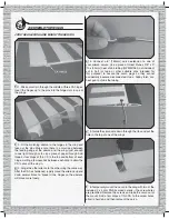
Страница 4: ...A has hardened rapidly move the ailerons up and down several times to break in the hinges so the ailerons will move more freely 4 Connect a 6 150mm servo extension to one of your aileron servos Use a piece of Great Planes 3 8 x 3 10 x 80mm heat shrink tubing GPMM1060 not included cut in half or tape or other suitable clips intended for this purpose to secure the servo plugs so they cannot accident...

Страница 5: ...LLIPS SCREWS 2 Enlarge the holes in one of the control horns included with this kit with a 57 043 1mm drill or a hobby knife so the aileron pushrod wire will fit Drill 5 64 2mm or 3 32 2 4mm holes through the aileron for the horn mounting screws and hook up the aileron as shown note in the photo that the horn is located on the aileron so the pushrod will be perpendicular to the wing trailing edge ...

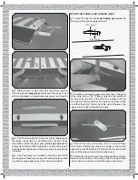
Страница 6: ...E WHEELS AND LANDING GEAR 1 Insert the right and left main landing gear wires into the wing so they will be angled forward 3 32 2mm 3 32 2mm 2 Holding a flat landing gear strap over one of the gears in the wing drill a 1 16 1 6mm hole into the bottom of the wing using the hole in the strap as a guide note that the strap must be mounted at an angle so the holes will be no farther than 3 32 2mm from...

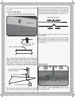
Страница 7: ...hrod guide tube located just under the leading edge of the slot for the horizontal stabilizer and from the exit slot for the rudder pushrod guide tube located just behind and below the slot for the vertical stabilizer The stab is shown already in position but yours should not yet be in place 2 Temporarily join the elevators to the horizontal stabilizer stab with two hinges in each side at this tim...

Страница 8: ...stab and take out the hinges Install the stab into the fuselage Taking accurate measurements from side to side center the trailing edge by equalizing the distance between both ends of the stab and the fuselage 7 Once the stab is centered stick pins into the trailing edge tightly to both sides of the fuselage holding the trailing edge in place 8 Stick another pin into the top of the front of the fu...

Страница 9: ...ing Cut the covering from the bottom of the wing around the wing bolt hole for the plywood wing bolt washer Glue the washer into position while simultaneously mounting the wing to the fuselage with a 3 x 20mm Phillips screw and a 3mm washer The wing will be used as a reference for stab alignment in the following steps 14 Use coarse sandpaper to roughen the elevator joiner wire so glue will adhere ...

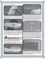
Страница 10: ...ng from the tail gear hole on the bottom of the fuselage then insert the tail gear assembly backwards as shown Once you get the gear up into position through the slot in the horizontal stab turn it around the other way as shown 3 The same as was done for the horizontal stabilizer fit the vertical stabilizer fin into the fuselage Use a fine point felt tip pen to mark the fuselage on both sides and ...

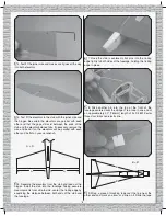
Страница 11: ...od wires to the second from the outer hole of a control horn Slide the wire up into the rudder guide tube in the fuselage Then mount the horn to the rudder the same way the horns were mounted to the ailerons by drilling 5 64 2mm or 3 32 2 4mm holes for the screws and mounting the horn with two 2 x 10mm machine thread Phillips screws and the horn mounting plate on the other side 3 Connect the other...

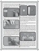
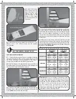
Страница 12: ... lock connectors and tighten them down Cut the pushrods approximately 1 2 10mm past the screw locks MOUNT THE MOTOR AND ESC 1 Guide the motor wires through the hole in the firewall and mount the motor with three 3 x 8mm Phillips screws and a drop of threadlocker on the threads 2 Fit then glue the plywood ESC mounting plate into position 3 Mount the ESC to the ESC mounting plate with double side fo...

Страница 13: ...uded Checking to be sure the red and white paint line on the cowl aligns with the red and white covering on the fuselage tape the cowl into position also make sure the cowl is centered over the propeller shaft and there will be approximately 1 8 3mm clearance between the front of the propeller and the cowl 8 Using the holes in the templates as a guide drill 1 16 1 6mm holes through the cowl into t...

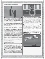
Страница 14: ...nsion wire to the receiver Use double sided foam mounting tape to mount the receiver where desired If your receiver is small enough it could be mounted next to the battery on the left side of the fuselage but this one was mounted behind the battery 4 If using a 2 4GHz receiver cut pieces of the small tubing supplied and glue the tubes inside the fuselage for guiding the antennas If using a 72MHz r...

Страница 15: ... moves is the up elevator control throw Use the endpoint adjustment in your transmitter or move the screw lock pushrod connector in the elevator servo arm to a new hole to increase or decrease the throw as necessary 5 Measure and set the up and down and left and right control throws for all of the control surfaces If your radio does not have dual rates we recommend setting the throws at the high r...

Страница 16: ...ave the greatest effect on how a model flies and may determine whether or not your first flight will be successful If you value this model and wish to enjoy it for many flights DO NOT OVERLOOK THIS IMPORTANT PROCEDURE A model that is not properly balanced will be unstable and possibly unflyable At this stage the model should be completely ready to fly with all of the systems in place including the...

Страница 17: ...ance drop before the ESC cuts off motor power so when you notice the plane flying slower you should land Often but not always power can be briefly restored after the motor cuts off by holding the throttle stick all the way down for a few seconds To avoid an unexpected dead stick landing on your first flight set your alarm or timer to a conservative 4 minutes When the alarm sounds you can land your...

Страница 18: ...el to slow while it continues to descend Ideally in calm conditions you will be holding full up elevator at the point of touchdown If the conditions are breezy you may have to fly the model to the ground with a small amount of motor power and less up elevator Once the model touches down and has lost flying speed hold full up elevator to keep the tail down One final note about flying your Chipmunk ...

Страница 19: ...19 ...

Страница 20: ...Entire Contents 2012 Hobbico Inc All rights reserved GBGA1023 www carlgoldbergproducts com ...

Отзывы: