Carbatec CDC-850P, Manual
The Carbatec CDC-850P user manual is a must-have companion for owners of this powerful tool. With clear and concise instructions, this manual guides users through assembly, operation, and maintenance. Download it for free at manualshive.com to ensure you make the most of your Carbatec CDC-850P.
Share
Download


Reviews:
No comments
Related manuals for CDC-850P
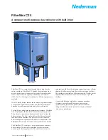
filtermax c25
Brand: Nederman Pages: 4

10-005 M1
Brand: General International Pages: 5

10-055
Brand: General International Pages: 18

10-510 M1
Brand: General International Pages: 20

10-800CF M1
Brand: General International Pages: 26

CBA-080AT2-HI
Brand: Chiko Pages: 25

CMP-2500AT3-A
Brand: CHIKO AIRTEC Pages: 69


