background image

Contents

1. Safety Precautions
2. Equipment Symbols
3. Cleaning Instructions
4. Disposal of the Unit
5. Application and Function Description
6. Features
7. Connection Method
6. Adjustment Method
7. Reference
7. Compatible Signals

8. Specifications

9. Contact Information

Display User's Manual

MD-DFM24-ENDO

1
4
6
7
8
9

10
12
36
37
38
40

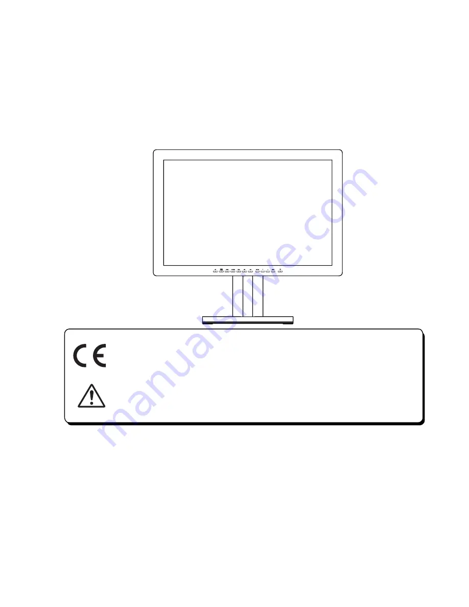
24-inch (61.1cm) Color LCD Display

Thank  you  for  purchasing  our  color  LCD 

Display.

Carefully read this User's Manual and use 

the product properly.  Before using it, also 

read "Safety Precautions."

Keep the User's Manual as close to you as 

possible and in safe custody.

If you have lost the manual, contact your 

dealer.  We will reissue a manual.

The names of companies and products are 

registered brand names or brand names.

Conformity according to the Council Directive 93/42/EEC concerning Medical 

Devices.

Use this product after carefully reading this Manual and understanding the 

contents.

Store this manual with care, as close as possible, so that you can read 

whenever necessary.

Summary of Contents for MD-DFM24-ENDO

Page 1: ...CD Display Carefully read this User s Manual and use the product properly Before using it also read Safety Precautions Keep the User s Manual as close to you as possible and in safe custody If you have lost the manual contact your dealer We will reissue a manual The names of companies and products are registered brand names or brand names Conformity according to the Council Directive 93 42 EEC con...

Page 2: ...Revision History The revision letter changes with related comments each time the document is updated Revision Comment A Initial release of this document ...

Page 3: ...IEC 60601 1 1 Safety requirements for medical electrical systems Equipment not complying with UL EN IEC 60601 1 shall be kept outside the patient environment as defined on the systems standard Safety Precautions IV Intended Use The intended use of the equipment is to display medical imaging data and endoscopy applications It is not allowed to operate the equipment with power supplies other than th...

Page 4: ...d the provided shielded video interface cable with bonded ferrite cores Also any unauthorized changes or modifications to this monitor would void the user s authority to operate this device VI Precautions 2 Make sure to carefully read the Operating Manual prior to using the monitor in order to properly use the monitor Note that excluding those cases where a responsibility for legal compensation is...

Page 5: ...icular if there are any unusual sounds or smells coming from it unplug the AC cable immediately and contact the manufacturer authorized or service center VII Environment Place the monitor on a flat and leveled surface Place the monitor in a well ventilated place Keep the monitor away from overly hot cold or humid places places directly under sunlight dusty surroundings equipment that generate stro...

Page 6: ...es with applicable US government Federal Communications Commission radio frequency interference regulations Fragile Handle with care Indicates front Keep dry Protect from rain Mercury This product consists of devices that may contain mercury which must be recycled or disposed of in accordance with local state or country laws ON Power connection to the mains Recycled materials or may be recycled St...

Page 7: ... be collected separately Please contact an authorized representative of the manufacturer for information concerning the decommissioning of your equipment ATTENTION Consult accompanying documents DANGER Shock Hazard Dangerous voltage To reduce the risk of electric shock do not remove cover Refer servicing to qualified service personnel ...

Page 8: ...liquids from the list below and use a soft lint free cloth to clean the screen 1 Water 2 Windex Blue glass surfaces only 3 Clorox Bleach Active Ingredient 5 25 Sodium Hypochlorite Off the Shelf Mix 10 1 with H2O 4 Sagrotan dilution 3 100 containing 75 mg tartaric acid per 100ml solution 5 Mild Soap ...

Page 9: ...r local regulations or rules upon dispose of this product Hg WARNING This product consists of devices that may contain mercury which must be recycled or disposed of in accordance with local state or country laws Within this product the backlight lamps in the display contain mercury 7 ...

Page 10: ...ghtness and contrast can be adjusted via the on screen menu The equipment supplied includes the signal cables the power supply with power cord and this user manual Transport Damage If the equipment has obviously been damage in transit make a written report immediately upon arrival of the goods and notify the shipping agent The shipping agent must be informed of hidden damage in transit in writing ...

Page 11: ...me Model No MD DFM24 ENDO Power Rating 24Vdc 4 6A The medical grade flat screen display must only be operated with the power supply Skynet Electronic SNP A159 Serial No Serial Number EN 60601 1 UL60601 1 CAN CSA 22 2 The device fulfills the requirements of the medical standard EN 60601 1 and cUL 60601 1 and CAN CSA 22 2 No 601 1 The symbol indicates compliance with the medical standard EN 60601 1 ...

Page 12: ...transformer or electrically isolated interface e g optocoupler This applies to devices of protection class I or II It is not permitted to integrate protection class 0 devices in medical electrical systems In the patient environment the following maximum enclosure leakage currents current flowing between two device enclosures or between the enclosure of a device and the protective earth conductor a...

Page 13: ...nment as a result of the proposed combination of devices Connecting medical electrical devices to other medical electrical devices and or other non medical electrical devices creates a medical system which must comply with the system standard EN 60601 1 1 cUL 60601 Before putting the system into service a specialist is required to ascertain its conformity with the system standard WARNING Personal ...

Page 14: ... cleaning agents directly onto the display Spray the cleaning agent onto a cloth and wipe the display clean without exerting any pressure Do not place any objects on the signal cables Route the signal cables and the power cable to the flat screen display such that they do not present a stumbling hazard CAUTION Personal Injury All devices used must comply with the applicable IEC EN or ISO standard ...

Page 15: ...ines and standards Directive Directive 93 42 EWG of the Council of 14 Jun 1993 Standards DIN EN 13485 2003 AC2007 Medical Products Quality management system IEC 60601 1 3rd Edition 2005 EN 60601 1 2007 General Requirements Of Basic Safety and Essential Performance EN 60601 1 2 2007 EMC Directive EMC Emission EMC Immunity EMC Tests have been carried out using standard cables with cables length of u...

Page 16: ...ns deteriorations and brightness drifts when power is turned on Gamma curve adjustments are made by OSD This is for various modality terminals medical image displays for PACS 1 and graphics Remote control port This color LCD display has the remote control port that controls the functions of the monitor Power management This unit has loaded the power management system The power management mode func...

Page 17: ...DVI connector of the monitor and the digital RGB output connector with the attached DVI cable 24 pin DVI Disconnect Device The following component is considered the equipment disconnect device AC Power Inlet Make sure you use the auxiliary AC Adapter Type SNP A159 Caution 1 Confirm that your computer is off Then confirm that the main switch of the color LCD monitor is off 15 ...

Page 18: ...nent video cable 3 Connect Video signal Cable for video device output Connect S Video connector of the LCD monitor and an S Video output device with the attached S Video cable For composite signal connect the BNC connector of the monitor and a composite video output device with the composite video cable 16 ...

Page 19: ...rmed while OSD is on screen Press Enter key execute select items save data Source select Pressing Source key VGA DVI HDMI changes the present source POWER indicator Power Power management display The indicator illuminates green when power normally on The indicator illuminates orange and the display turns off when power management function on or no signals The indicator goes out when power off DC p...

Page 20: ...og signal cable is plugged into this Digital input connector DVI Digital video signal input The provided digital signal cable is plugged into this This is available to a computer with a DVI digital video output Digital input connector HDMI Digital video signal input The provided digital signal cable is plugged into this This is available to a computer with a HDMI digital video output Control input...

Page 21: ...cations of the four screw holes in the bracket on the wall Step 3 Drill four pilot holes at the marked locations on the wall for the bracket retention screws Step 4 Align the wall mounting bracket screw holes with the pilot holes Step 5 Secure the mounting bracket to the wall by inserting the retention screws into the four pilot holes and tightening them Step 6 Insert the four monitor mounting scr...

Page 22: ...t Adjust the black level offset for the Main channel by the range from 0 to 100 Adjust the contrast for the Main channel by the range from 0 to 100 Adjust the saturation for the Main channel by the range from 0 to 100 Adjust the hue for the Main channel by the range from 0 to 100 Adjust the sharpness for the Main channel by the range from 0 to 24 Return to Exit of Image Setting page Adjust horizon...

Page 23: ...display Adjust the V size for Sub channel display Return to Exit of PIP Display of Multi PIP Settings page Adjust the H position for Sub channel display by the range from 0 to 100 Adjust the V position for Sub channel display by the range from 0 to 100 Swap source between Main and Sub channel Return to Exit of Multi PIP Settings page Adjust the black level offset for the Sub channel by the range f...

Page 24: ...Save Clear for New Timing Setting Provide HDMI source color space format select Automatically select the signal source Adjust the brightness for the indicator LED by the range from 0 to 100 Return to Main Menu Return to Exit of OSD Misc Adjust the H position for OSD by the range from 0 to 100 Adjust the V position for OSD by the range from 0 to 100 Return to Exit of OSD Misc Display OSD in English...

Page 25: ...om User1 Load all adjust settings from User2 Load all adjust settings from User3 Load all adjust settings from User4 Load all adjust settings from User5 Adjust OSD display time Adjust OSD display transparent Load Exit User 1 User 2 User 3 User 4 User 5 OSD Timer Transparent ...

Page 26: ... the Main Menu In addition this page will show below messages 1 Information for input timing of Main channel 2 Timing table provide by system 3 Indicate which source display for Main channel 4 Indicate which source display for Sub channel 5 Record how long time display for this monitor already Input Source Setting You can select source for Main channel from Analog VGA Digital HDMI S video CVBS YPb...

Page 27: ...n brightness contrast and the like of the screen When first using this color display or input new timing will perform this adjustment When Auto Adjusting disappear from the screen means it have finished the Auto Setup function Black Level Adjust the black level offset for the Main channel by the range from 0 to 100 Contrast Adjust the contrast for the Main channel by the range from 0 to 100 Notice...

Page 28: ... the sharpness for the Main channel by the range from 0 to 24 Display Adjust the Horizontal Vertical position clock phase for Main channel Exit Return to Exit of Image Setting page H Position Adjust horizontal screen position for Main channel by the range from 0 to 100 V Position Adjust vertical screen position for Main channel by the range from 0 to 100 12 Sharpness ...

Page 29: ...in channel so that the screen image appear crisp and focused Color Mode Settings Selecting this control allows you select color temperature or gamma curve Exit Return to Main Menu Color Temp Selecting this control allows you to select preset color temperature of Cool Neutral Warm or User for customized red green and blue levels Notice Only support on Analog VGA source Notice Only support on Analog...

Page 30: ...to modifications User Selecting this control allows you to adjust the Red gain Green gain and Blue gain individually to match personal preference Exit Return to Exit of Color Mode Settings page Red Gain You can adjusts the gain of Red by the range from 0 to 100 Green Gain You can adjusts the gain of Green by the range from 0 to 100 Blue Gain You can adjusts the gain of Blue by the range from 0 to ...

Page 31: ...turn to Exit of Color Mode Settings page Gamma 1 8 Set Gamma curve to curve 1 8 Gamma 2 0 Set Gamma curve to curve 2 0 Gamma 2 2 Set Gamma curve to curve 2 2 Gamma 2 4 Set Gamma curve to curve 2 4 Calibration Set Gamma curve to calibration mode DICOM Set Gamma curve for medical standards 29 ...

Page 32: ...YPbPr PCbCr RGBS Gray area are not available to choose Please find the below matrix to see the combinations for Main channel with Sub channel if you set to PIP mode or POP mode Notice PIP Display Swap PIP Picture only active when PIP Mode set to PIP or POP Main channel Sub channel VGA DVI HDMI S video CVBS YPbPr RGBS SDI VGA X O O O O O X O DVI O X X O O O O O HDMI O X X O O O O O S video O O O X ...

Page 33: ...ge PIP Size Adjust the H size for Sub channel display PIP H Size Adjust the V size for Sub channel display PIP Position Selecting this control allows you to adjust the position for Sub channel Exit Return to Exit of PIP Display of Multi PIP Settings page PIP H Position Adjust the H position for Sub channel display by the range from 0 to 100 PIP V Position Adjust the V position for Sub channel disp...

Page 34: ... contrast for the Sub channel by the range from 0 to 100 Saturation Adjust the saturation for the Sub channel by the range from 0 to 100 Hue Adjust the hue for the Sub channel by the range from 0 to 100 Sharpness Adjust the sharpness for the Sub channel by the range from 0 to 24 Management Settings Selecting this control allows you to adjust below items settings for Main channel Notice Only suppor...

Page 35: ... H size for Main channel display Ver Zoom Adjust the V size for Main channel display Recall Select this function to recall all OSD adjustments to the factory default settings and delete the specify User setting you used Ex If you load User1 from Preset Save page the system will clear User 1 after you press recall Auto Adjustment Select this function to on or off Auto Adjustment Function Monochrome...

Page 36: ... the several timings which have been fine tune successfully Refer to the details on page 30 Save Timing section Exit Return to Exit of Management Settings page Execute Execute New Timing Search that wasn t in the preset timing table Aspect Adjust the display ratio of the video signals for Main channel active after press Execute default was disable this function Clock Adjust the clock for the video...

Page 37: ... signal connected to the VGA or RGBS BNC can be stored as two different user modes The display memory can contain maximum 16 different users modes VGA and RGBS source can store separately When the memory is full user can use clear timing to clear some of the 16 modes when a new video signal is adjusted You can save the new timing after you press Execute totally can save sixteen timings 1 Choose sa...

Page 38: ... HDMI Video Format Provide HDMI video format select for HDMI source for Main and Sub channel both There are auto YCbCr4 4 4 YCbCr4 2 2 RGB 4 models Default is set to Auto that monitor auto detect input color space If monitor show wrong color under HDMI source you can manual select color space to YCbCr4 4 4 4 2 2 or RGB Auto Source Automatically select the signal source LED Drive Adjust the brightn...

Page 39: ...r OSD Exit Return to Main Menu OSD Position Selecting this control allows you to adjust position for OSD Exit Return to Exit of OSD Misc OSD H Position Adjust the H position for OSD by the range from 0 to 100 OSD V Position Adjust the V position for OSD by the range from 0 to 100 ...

Page 40: ...ow languages that you want to display for OSD Exit Return to Exit of OSD Misc English Display OSD in English Francais Display OSD in French Deutsch Display OSD in German Italiano Display OSD in Italian Espanol Display OSD in Spanish 日本語 Display OSD in Japanese ...

Page 41: ...t then save into five User settings Exit Return to Exit of OSD Misc Save Save OSD setting after you adjust into five User settings separately Exit Return to Exit of Preset Save of OSD Misc User 1 Save all adjust settings to User 1 User 2 Save all adjust settings to User 2 User 3 Save all adjust settings to User 3 User 4 Save all adjust settings to User 4 User 5 Save all adjust settings to User 5 3...

Page 42: ...r 2 Load all adjust settings to User 2 User 3 Load all adjust settings to User 3 User 4 Load all adjust settings to User 4 User 5 Load all adjust settings to User 5 OSD Timer Adjust OSD display time that support 5 10 15 20 25 30 OSD will not disappear if set to 0 OSD will disappear after 5 sec if set to 5 just like that for 10 15 20 25 30 Transparent Adjust OSD display transparent from 0 to 7 by o...

Page 43: ... device in advance on start up of Windows 98 Me 2000 or Windows XP and sets the detailed information of the color LCD display in the system file in order to achieve Plug Play Data reading from the color LCD display is done through a video signal cable which needs to be connected when Windows 95 98 Me 2000 or Windows XP is on DDC 1 Note 1DDC Display Data channel and 2 VESA are registered trademarks...

Page 44: ...8 68 85 00 SXGA 1280 1024 63 98 60 02 1280 1024 79 98 75 03 UXGA 1600 1200 75 0 60 0 WUXGA 1920 1200 73 4 59 5 720 X 400 720 400 31 47 70 09 1024 X 940 1024 940 30 69 30 1024 X 1024 1024 1024 31 22 25 Mac 640 480 35 0 67 832 624 49 7 75 1024 768 60 2 75 576 50i PAL 15 625 50 480 60i NTSC 15 734 60 576 50P 31 250 50 480 60P 31 469 60 720 50p 37 500 50 720 60p 45 000 60 1080 50i 28 125 50 1080 60i 3...

Page 45: ...85mm x Depth 237mm x Height 539mm with base Width 585mm x Depth 98mm x Height 390mm without base Approx 10 8 kg with base 8 2 kg without base Response Time TrR 6 ms Typ TrD 7 ms Typ Brightness 400 cd m2 Typ 320 cd m2 Min Contrast Ratio 1000 1 Typ 1 VGA 15 pin D SUB Video signal Analog RGB 0 714Vp p 75Ω Horizontal sync and composite sync signal TTL level 2 5 5 5V plus minus 2 HDMI 19 pin HDMI conne...

Page 46: ...44 External Dimensions with base External Dimensions without base 236 5 ...

Page 47: ... Full application support and service is available For technical support or service problems please contact our service team at Canvys Visual Technology Solutions A Division of Richardson Electronics GmbH Raiffeisenstr 5 78166 Donaueschingen Germany Tel 49 0 771 8300 0 Fax 49 0 771 8300 80 Email info europe canvys com Internet http www canvys com ...

Page 48: ...A number under the following link http teklink rell com MRcgi MRentrancePage pl After receipt of the equipment for repair we will send you an order confirmation and a cost estimate for repairs after the warranty period For questions about servicing and repairs please call your contact in our Sales team There you will receive more detailed information about handling service and repair cases 46 ...

Page 49: ...ronics GmbH Claims for warranty defects shall not exist in cases of improper usage modification of the goods by the customer using the goods outside its field of application or its electrical specifications neglect or misuse of the goods by the customer natural wear and tear and damages defects reduced output and changes of conditions or operation of our goods due to extraneous causes e g impact b...

Page 50: ...Manufacturer Canvys Visual Technology Solutions A Division of Richardson Electronics GmbH Raiffeisenstr 5 78166 Donaueschingen Tel 49 0 771 8300 0 Fax 49 0 771 8300 80 Email info europe canvys com Internet http www canvys com ...

Page 51: ...GEN LCD Display Model GEN2410LMII ...

Reviews: