CAN CU3002, Instruction Booklet
Discover the CAN CU3002 instruction booklet and enhance your user experience! This comprehensive manual offers detailed guidance, ensuring you maximize the product's benefits. Download the free manual directly from manualshive.com and start mastering your CAN CU3002 today!
Share
Download


Reviews:
No comments
Related manuals for CU3002

Toledo 90 Dual Fuel
Brand: Falcon Pages: 40

900S Dual Fuel
Brand: Falcon Pages: 29

Renown
Brand: Parkinson Cowan Pages: 39

RIC-SNG28S
Brand: Rasonic Pages: 18

JEA73
Brand: Judge Pages: 6

SG 414
Brand: Parkinson Cowan Pages: 48

VI 230
Brand: Gaggenau Pages: 16

GP24WK
Brand: Thermador Pages: 94

JNP-1000
Brand: Tiger Pages: 26

PP912KMCC
Brand: GE Pages: 2

JER8785QAF
Brand: Jenn-Air Pages: 96

ED-15THSE
Brand: Garland Pages: 2

HD-26
Brand: Morrone Pages: 48

5865
Brand: Crock-Pot Pages: 9
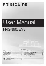
FNGN90JEYS
Brand: Frigidaire Pages: 40
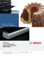
HGD43A120S/03
Brand: Bosch Pages: 76

HA422510M
Brand: Siemens Pages: 24

HEV 35.1
Brand: Siemens Pages: 40


