background image


SmartSwitch 9000

9F241-12

User’s Guide


9031203-01

Summary of Contents for 9F241-12

Page 1: ...SmartSwitch 9000 9F241 12 User s Guide 9031203 01...

Page 2: ......

Page 3: ...AMAGES WHATSOEVER INCLUDING BUT NOT LIMITED TO LOST PROFITS ARISING OUT OF OR RELATED TO THIS MANUAL OR THE INFORMATION CONTAINED IN IT EVEN IF CABLETRON SYSTEMS HAS BEEN ADVISED OF KNOWN OR SHOULD HA...

Page 4: ...in which case the user will be required to correct the interference at his own expense WARNING Changes or modifications made to this device which are not expressly approved by the party responsible fo...

Page 5: ...Equipment for use in a Commercial or Light Industrial Environment We the undersigned hereby declare under our sole responsibility that the equipment packaged with this notice conforms to the above di...

Page 6: ...Notice iv...

Page 7: ...witch 2 3 Installing the Module into the SmartSwitch 9000 Chassis 2 5 The Reset Switch 2 7 Chapter 3 Operation Flexible Network Bus FNB 3 1 System Management Buses 3 2 SMB 1 Bus 3 2 SMB 10 Bus 3 2 Sys...

Page 8: ...Contents vi...

Page 9: ...ocessor The 9F241 12 is equipped with an advanced Intel i960 microprocessor This microprocessor provides a platform for all management functions within a scalable RISC based architecture Management Ma...

Page 10: ...built in visual diagnostic and status monitoring system With LANVIEW LEDs you can quickly identify the device port and physical layer status at a glance Hot Swapping The 9F241 12 can be installed or r...

Page 11: ...1 3 Introduction Figure 1 1 The 9F241 12 module 1 5 M 1 M 2 M 3 M 4 M 5 M 6 M 9 M 10 9 4 8 12 M 7 M 8 M 11 M 12 SMB CPU FNB 9F241 12 FDDI...

Page 12: ...ing mode switches rebooting the unit etc The serial and revision numbers of all involved Cabletron Systems products in the network A description of your network environment layout cable type etc Netwo...

Page 13: ...precautions to prevent damage from Electrostatic Discharge ESD 3 Carefully examine the module checking for damage If any damage exists DO NOT install the module Contact Cabletron Systems Technical Su...

Page 14: ...Installing the MicroLAN Module 2 2 Figure 2 1 User Accessible Components SMB 1 PROM i960 Processor Flash SIMM Socket Boot PROM DIP Switch...

Page 15: ...ing the Module Card DIP Switch An eight position DIP switch is located on the module card as shown in Figure 2 1 and Figure 2 2 The functions of the switches are listed in Table 2 1 Figure 2 2 Locatio...

Page 16: ...ers which are stored in NVRAM when the module is powered down and remain there until the switch is toggled again 6 Force BootP Download Toggling this switch after pulling the board out of the SmartSwi...

Page 17: ...le is being mounted in All other slots must be covered if modules are not being installed to ensure proper airflow and cooling 3 Attach one end of the ESD wrist strap packaged with the SmartSwitch 900...

Page 18: ...ing the SmartSwitch 9000 Module Metal Back Panel Module Guides Module Jack for ESD Wrist Strap Plastic Tab Warning Ensure that the circuit card is between the card guides Lock down the top and bottom...

Page 19: ...ressing the Reset switch twice within three seconds causes the processor i960 to reset Pressing and holding the switch on for three or more seconds causes the module to shutdown Pressing and holding i...

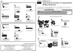
Page 20: ...Installing the MicroLAN Module 2 8...

Page 21: ...ock Diagram Flexible Network Bus FNB The FNB consists of two dual FDDI networks FNB 1 and FNB 2 providing up to 400 Mbps of data bandwidth These FDDI networks are 100 ANSI FDDI compliant supporting SM...

Page 22: ...Interface Module EPIM located on the front of the Environmental Module Through an EPIM connection full SNMP management of the SmartSwitch 9000 is available out of band from user data Modules that sha...

Page 23: ...12 module has a dual attachment to the FNB backplane connecting to both FNB 1 and FNB 2 The module can insert into the FNB or bypass it These flexible configuration options make the SmartSwitch 9000 i...

Page 24: ...Operation 3 4...

Page 25: ...the status of the module and may be used as an aid in troubleshooting Shown in Figure 4 1 is the LANVIEW LEDs of the concentrator modules Figure 4 1 The LANVIEW LEDs 1 5 M 1 9 4 8 12 SMB CPU FNB 9F241...

Page 26: ...s LED Color State Description Green Functional Fully operational Yellow Crippled Not fully operational i e one bad port Yellow Green Booting Blinks yellow and green while booting Red Reset Normal powe...

Page 27: ...he functions of the FDDI Port LEDs are listed in Table 4 4 Table 4 4 FDDI Status LEDs LED Color State Green Link Activity Port enabled Yellow Link No Activity Port enabled Red No link Port disabled Re...

Page 28: ...LANVIEW LEDs 4 4...

Page 29: ...EN 55022 Class A VCCI Class I EMC the following requirements EN 50082 1 IEC 801 2 ESD IEC 801 3 Radiated susceptibility IEC 801 4 EFT Service MTBF MHBK 217E 200 000 hrs MTTR 0 5 hr It is the responsib...

Page 30: ...4 0 H x 3 0 W centimeters 13 8 D x 17 4 H x 1 2 W inches Weight Unit 1360 7 gr 3 lb Shipping 1814 4 gr 4 lb Link Distance Up to two kilometers on multimode fiber optic cable as specified by ANSI MMF P...

Reviews: