C.T.M. HS-1000, User Manual
The Omnitronic HS-1000 User Manual is your ultimate guide to mastering this state-of-the-art audio device. Download our free manual from manualshive.com to explore all the incredible features, settings, and functions, ensuring you get the most out of your HS-1000 experience.
Share
Download


Reviews:
No comments
Related manuals for HS-1000

Roxx NO
Brand: Decon wheel Pages: 5

Dash Series
Brand: R Healthcare Pages: 52

Start M2
Brand: Otto Bock Pages: 36

WCR1616E
Brand: Probasics Pages: 22

70019-Y-BAT
Brand: LINE2design Pages: 8

KLICK Power Limited Edition
Brand: Klaxon Pages: 37

600 XL
Brand: Quantum Rehab Pages: 59

1500
Brand: Roma Medical Pages: 16

Panda Futura 89539
Brand: R82 Pages: 6
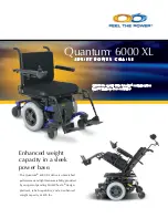
6000 XL
Brand: Quantum Pages: 2

Economy L97792
Brand: NRS Healthcare Pages: 2

TA iQ
Brand: TA Service Pages: 50

Combi
Brand: Levo Pages: 63

Atigra Mid Wheel Drive
Brand: AC Mobility Pages: 23

SAFER-IVC
Brand: Safer Locks Pages: 2

LIAM SEATING
Brand: You-Q Pages: 28

QLASS
Brand: You-Q Pages: 72

KM-8020
Brand: Karma Pages: 44


