


English
Type of
manual1
Operating manual
Machine1
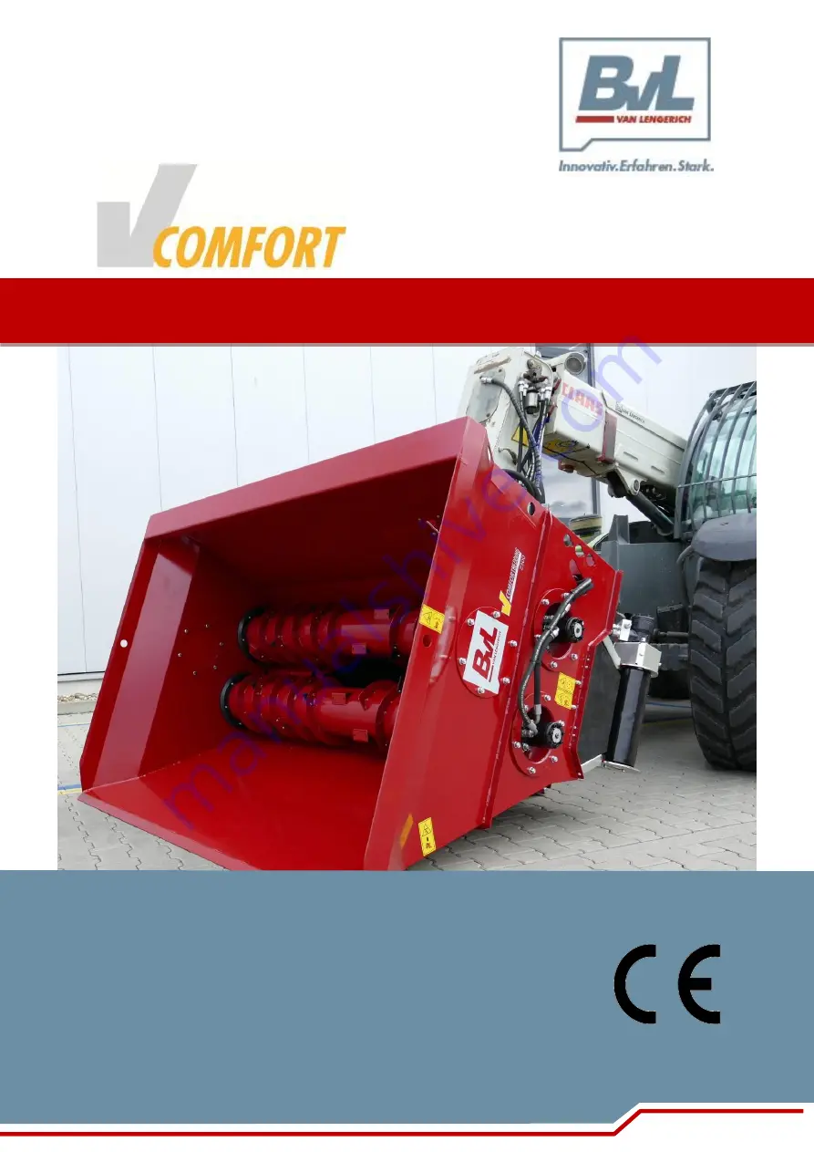
V-COMFORT Bedding
MachineNo
1
116588
MachineTy
pe1
Machine
Version1
1.1
Order
K20_417
CustomerN
ame1
Bernard van Lengerich
CustomerA
ddress1
Grenzstraße 16
CustomerL
ocation1
D-48488 Emsbüren
CustomerP
hone1
+ 49 (0)5903 951-0
CustomerC
ountry1
Germany
CustomerF
ax1
Enter customer fax hereCustomerEmail1 Enter customer email here
Date
created
2/3/20
File name
BA_V-COMFORT_Bedding_EN
Supplemen
t1
Supplemen
t2
Year of
manufactur
e1
Operating manual
www.bvl-group.de
V
-COMFORT Bedding
Type 2300 / 2600 / 3000
Rev. 1 / 03.20 Item no. 117194
Printed in Germany – translation of the original operating
manual
Read and follow this operating manual before putting the machine into operation for the first time!
Store for future reference!
Type of
manual1
Operating manual
Machine1
Mixer wagon
MachineNo1
XXX
MachineType1
Machine
Version1
1.1
Order
Order 1
CustomerName
1
Bernard van Lengerich
CustomerAddre
ss1
Grenzstraße 16
CustomerLocati
on1
D-48488 Emsbüren
CustomerPhone
1
+ 49 (0)5903 951-0
CustomerCount
ry1
Germany
CustomerFax1
+ 49 (0)5903 951-34
CustomerEmail
1
Date created
11/5/19
File name
BA_V_MIX_PLUS_EN
Supplement1
Supplement2
Year of
manufacture1
2019


