


March 2011
Page
1
of
30
FF06-6P (Version 2.07)
User Guide
2013
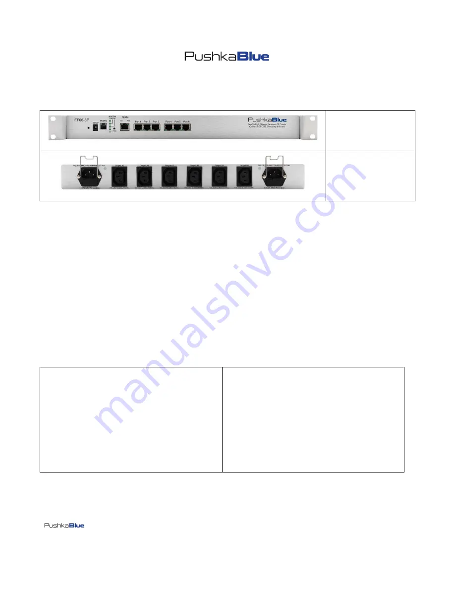
Front View
Rear View
PLEASE NOTE: THIS PRODUCT IS NOT APPROVED FOR USE IN CHINA
All Rights Reserved (C) Copyright 2002-2011, Pushkablue Data Communications Ltd
Pushkablue Data Communications Ltd
100, Alexandra Road, Poole, Dorset, BH14 9EP, United Kingdom
Tel: +44 (0) 1202 606285
Tel from U.S.A. (Toll Free): 1 866 895 3130
Email: [email protected]
No part of this publication may be reproduced, transmitted, transcribed, stored in a retrieval system, or translated into any language or computer language, in any form or by any means, electronic,
mechanical, magnetic, optical, chemical, manual or otherwise, without the prior written permission of Pushkablue Data Communications Ltd
Disclaimer
Pushkablue Data Communications Ltd makes no representations or warranties with respect to the contents hereof and specially disclaims any implied warranties or merchantability or fitness for any
particular purpose. Further, Pushkablue Data Communications Ltd reserves the right to revise this publication and to make changes from time to time in the content hereof without obligation of
Pushkablue Data Communications Ltd to notify any such person of such revision or changes.
Trademarks
The Trademarks of the other Corporations which may be used in this manual are hereby acknowledged.
Warning: This Product may contain chemicals Known to the State of California to cause Cancer, and/or Birth Defects or Other Reproductive harm
Specifications:
1 x Multitech MT5600SMI Internal V34 Globally approved Modem
(MT5600SMI Conformity: UL 60590-1 (UL No: E150299)
EN60950:2000, EN55022:1994+A1:1995+A2:1997
EN55024:1998, TBR21:1998, FCC Part 68)
See Multitech Declaration of Conformity on Page 32 of this document
1 x RJ45 Serial Input (9,600bps, 8, N, 1)
6 x Serial ports (Speeds 9600bps, 115,200bps)
2 x AC (C13) Input 10 Amps 100-240VAC 50-60Hz
6 x AC (C14) Output 10 Amps 100-240VAC 50-60Hz
1 x External Autosensing 100-250VAC Power Adapter 5VDC (2.6amps)
1 x DC Input 5VDC (1Amp Max)
Dimensions:
435mm (W) x 44mm (H) x 400mm (D)
1U Rackmount
Weight:
2.5Kgs ( 5.5lbs)
Enclosure:
Aluminium
Humidity:
10-80% non condensing
Operating Temperature:
-10 to 45º C
Conformity:
IEC 60950-1:2001
UL: 60950-1
CISPR 22/A1:2004
CISPR 24/A2:2002 FCC CFR47: Part 15: 2006
Please note:
This product does not have Homologation approvals for the following countries:
Mainland China,
Morocco, Peru, Tunisia, and Vietnam
.
Please contact Pushkablue Data Communications Ltd for homologation status.


