BRUSA Elektronik AG
Neudorf 14
CH
–9466 Sennwald
+41 81 758 19 00
[email protected]
www.brusa.biz
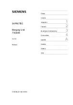
PDU254
ASM
TECHNICAL DATA
AND START-UP
Translation of the original German operating instructions
The Brusa PDU254 Series user manual provides detailed technical data and start-up instructions for this high-quality product. Download your free manual from manualshive.com to ensure proper installation and optimal performance. Take advantage of this valuable resource to get the most out of your Brusa PDU254 Series device.
BRUSA Elektronik AG
Neudorf 14
CH
–9466 Sennwald
+41 81 758 19 00
[email protected]
www.brusa.biz
PDU254
ASM
TECHNICAL DATA
AND START-UP
Translation of the original German operating instructions