Browan BW1250, User Manual
The Browan BW1250 User Manual is an essential companion for users of this high-quality product. Seamlessly combining performance and convenience, this manual provides comprehensive instructions to maximize the product's potential. You can easily download this manual for free from our website, ensuring a hassle-free user experience.
Share
Download


Reviews:
No comments
Related manuals for BW1250

DWL-1000AP+
Brand: D-Link Pages: 40

DAP-600P
Brand: D-Link Pages: 46

DAP-3310
Brand: D-Link Pages: 24

DWL-3200A
Brand: D-Link Pages: 23
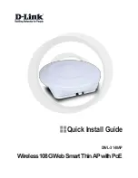
DWL-3140AP - Web Smart PoE Thin Access Point
Brand: D-Link Pages: 72

DAP-400P
Brand: D-Link Pages: 46

DWL-2130AP - xStack - Wireless Access Point
Brand: D-Link Pages: 12

DBA-1210P
Brand: D-Link Pages: 8

DWL-2230AP - xStack - Wireless Access Point
Brand: D-Link Pages: 12

DWL-2100AP - AirPlus Xtreme G
Brand: D-Link Pages: 2
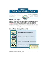
DWL-1000AP+
Brand: D-Link Pages: 8

DI-713
Brand: D-Link Pages: 5

DWL-3200AP - AirPremier - Wireless Access Point
Brand: D-Link Pages: 113

DAP-3666
Brand: D-Link Pages: 16

DAP-3320
Brand: D-Link Pages: 32

DI-713
Brand: D-Link Pages: 41

DWL-7230AP - xStack - Wireless Access Point
Brand: D-Link Pages: 12

DWL-2100AP - AirPlus Xtreme G
Brand: D-Link Pages: 180


