Brother S-7220B, Instruction Manual
The Brother S-7220B is a highly efficient sewing machine built for professional use. To master its wide range of functions, ensure optimum performance, and unlock its full potential, download the comprehensive Instruction Manual for free from our website. Discover step-by-step guidance and expert tips to achieve remarkable sewing results.
Share
Download


Reviews:
No comments
Related manuals for S-7220B

Sydney
Brand: Kangaroo Pages: 36

107-1
Brand: Singer Pages: 8

Lazy Kate
Brand: Nancy’s Knit Knacks Pages: 2
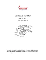
VERSA SF-S0870
Brand: Sunny Pages: 7

Minoltafax 1400
Brand: Konica Minolta Pages: 157

XCA4510
Brand: Uniden Pages: 95

Iris 10
Brand: Texi Pages: 34

52-56
Brand: Singer Pages: 67

MMg base
Brand: Fimap Pages: 44

885-V95
Brand: Brother Pages: 204
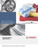
WAE24367UK
Brand: Bosch Pages: 36

56382452
Brand: Nilfisk-Advance Pages: 28

CombBind C20
Brand: GBC Pages: 9

LASERFAX 920
Brand: Philips Pages: 2

HFC 242
Brand: Philips Pages: 20

MF-JET 500
Brand: Philips Pages: 36
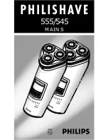
Philishave 555
Brand: Philips Pages: 38

PPF 450
Brand: Philips Pages: 40


