background image


\BETRANL\E16x442e


I E16x442   Rev: 00


26.11.2014


Page 1 of 73


D 71334   Waiblingen-Hegnach 
 

Esslinger Str. 26  

Tel.: 

+49 (0)7151/956230 

Fax: 

+49 (0)7151/956250 

E-Mail:   [email protected] 
Internet:  www.braun-tacho.de 
 

Quality certified according ISO 9001 

Monitor  A 

Monitor  B 

Monitor  C 


E1691 


P


E


E1665 

Trip 

SP3


RPM 

P


E


E1665 

Trip 

SP3


RPM 

P


E


E1665 

Trip


SP3


RPM 

Monitor  A 

Monitor  B 

Monitor  C 

SIL2/IEC61508


SIL2/IEC61508


SIL2/IEC61508


Test Interface 


Original Manual 

of 

Protection-System E16x442 

with 

Overspeed Protection 

and   

Voters for external Trip Release Conditions 


IEC61508;SIL2 and API670 compliant 


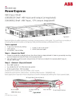
Figure 1:   E16x442 System Front View 

Summary of Contents for E16x442

Page 1: ...ording ISO 9001 Monitor A Monitor B Monitor C E1691 P E E1665 1 2 3 4 Trip SP3 RPM P E E1665 1 2 3 4 Trip SP3 RPM P E E1665 1 2 3 4 Trip SP3 RPM Monitor A Monitor B Monitor C SIL2 IEC61508 SIL2 IEC615...

Page 2: ...6 Inputs Test I Test II Test III 19 2 2 7 Inputs Starter Override of SP2 19 2 2 8 Inputs SP1B valid 19 2 2 9 This chapter is left blank intentionally 19 2 2 10 Inputs for Voter 1 19 2 2 11 Inputs for...

Page 3: ...of Monitor E1665 32 5 1 Display and Frontside Operational Elements 32 5 1 1 Front View of Monitor E1665 32 5 1 2 Status LEDs 32 5 1 3 Display during Test Procedures 32 5 1 4 Values accessible during n...

Page 4: ...m 1 of 3 13 Figure 5 E16x442 System Wiring Diagram 2 of 3 14 Figure 6 E16x442 System Wiring Diagram 3 of 3 15 Figure 7 Position of terminal blocks with version E16E442 16 Figure 8 Position of terminal...

Page 5: ...technical Commission incl inclusive IPxx Ingress Protection Number xx according to DIN EN 60529 ISO International Organization for Standardization LED Light Emitting Diode LOx Logic Output x max maxim...

Page 6: ...I E16x442 Rev 00 Page 6 of 73 Abbreviation Meaning 1oo2 1 out of 2 voting logic 1oo3 1 out of 3 voting logic 2oo2 2 out of 2 voting logic 2oo3 2 out of 3 voting logic...

Page 7: ...n by their voters 1oo2 2oo2 2oo3 or 3oo3 logic selectable 1 4 Key Features of System E16x442 Trip Release Function is SIL2 IEC61508 compliant as stand alone unit without external testing by DCS or by...

Page 8: ...E16x442 abc E16x442 abc c 1 Speed Signal Inputs and power supply for A5S sensors c 2 Speed Signal Inputs and power supply for Eddy Current Sensors c 3 Speed Signal Inputs for MPU magnetic pick up b 1...

Page 9: ...tor The trip release ability of a 2oo3 solenoid valve block can be verified by external 1 7 2 Test of 2oo3 solenoid valve block Test can only be performed if the Monitors are not in trip status The te...

Page 10: ...tic fields Air gap variations between machine and sensor do not create false signals With versions E16x442 xx2 Three Speed signals from Eddy Current Sensors or from MPUs are evaluated With versions E1...

Page 11: ...on System Backplane forming six 2oo3 Trip Lines fT F R fB F R fC B A C Pole Wheel Sensor to all modules Test I Test II Test III E1691 Test interface Test Frequency fT F R fC Test III F R fB F R fA fT...

Page 12: ...ter Soft ware Voter Soft ware Voter Soft ware Voter Soft ware Voter Soft ware Voter Soft ware Voter Soft ware Voter Soft ware Voter Soft ware Voter Soft ware Voter Soft ware Voter Soft ware Voter Soft...

Page 13: ...N L N L N Rev 02 06 2013 Logic Signal Inputs Reference terminals 3 X1 9 X1 3 X15 of Power Supply 1 X1_ 2 X1_ 3 X1_ 8 X1_ 9 X1_ 14 X1_ 15 X1_ 4 X1_ 5 X1_ 10 X1_ 11 X1_ 16 X1_ 17 X1_ 6 X1_ 7 X1_ 12 X1_...

Page 14: ...oter 5 Signal Inputs of Voter 6 Speed Trip Logic Output see 2 3 7 Monitor A Monitor B Monitor C Trip Voter 6 alternative n SP6 LO6 Trip Voter 5 alternative n SP5 LO5 Trip Voter 4 alternative n SP4 LO4...

Page 15: ...A5S B A D S 1 3 4 2 1 X3 1 X4 1 X5 2 X3 2 X4 2 X5 3 X3 3 X4 3 X5 5 X3 5 X4 5 X5 4 X3 4 X4 4 X5 brown green white yellow or red Cable screen must be connected to screen bar Marks for BRAUN cable leads...

Page 16: ...I E16x442 Rev 00 Page 16 of 73 2 1 7 Position of Terminal Blocks with Version E16E442 Figure 7 Position of terminal blocks with version E16E442...

Page 17: ...I E16x442 Rev 00 Page 17 of 73 2 1 8 Position of Terminal Blocks with version E16A442 Figure 8 Position of terminal blocks with version E16A442 shown is version E16A446...

Page 18: ...42 xx3 The signal inputs match the values of MPUs The speed signal inputs are rated SIL2 IEC61508 if the sensor supplier guarantees that the sensors will not give erratic speed signals due to a common...

Page 19: ...al Data of inputs see 3 1 3 2 2 9 This chapter is left blank intentionally 2 2 10 Inputs for Voter 1 The input signals for Voter 1 are internally connected to all monitors in parallel The input load o...

Page 20: ...tions is true Monitor releases trip due to overspeed resp voter if selected Selection in step P02 11 of E1665 Deviation of its own sensors versus both sensors of neighbor Monitors if monitored Selecti...

Page 21: ...Output is rated SIL2 IEC61508 Technical Data of output see 3 2 4 2 3 8 Output Trip Line IV V VI The Trip Lines IV V VI are 2oo3 circuits formed by contacts of safety trip relays IV and V of Monitors...

Page 22: ...ts trip status via the Test Interface as a logic signal to the periphery Output high no trip Output low trip Note The outputs have a delay of approx 10 seconds versus the trip of the monitor The Outpu...

Page 23: ...and serves for the upload of status and diagnostics of the system to a PLC or DCS 2 5 2 RS232 Interface with Interface Software IS RS232 E16 for OEM only The RS232 Interface in conjunction with the I...

Page 24: ...Vpp Impedance approx 47 kohms Sensor Supply only with versions E16x442 xx2 approx 24 volts maximum 120 mamps Inputs are free floating The sensor inputs have the same common but are free floating versu...

Page 25: ...hort circuit proof and free floating also versus each other 3 2 3 Technical Data of Opto Relay Outputs Maximum rating 50 volts dc 50 mamps Outputs are passive short circuit proof and free floating als...

Page 26: ...ximum rating 50 volts dc 3 amps 75 watts Maximum rating for DC13 applications 24 volts 3 amps Outputs are not short circuit proof permanent currents exceeding 8 amps will destroy outputs Impedance 10...

Page 27: ...or Conductor cross section solid min 0 2 mm Conductor cross section solid max 1 5 mm Conductor cross section stranded min 0 2 mm Conductor cross section stranded max 1 5 mm Conductor cross section str...

Page 28: ...e terminals all dimensions in mm Drawing not to scale wiring from top and bottom 13 88 220 201 5 109 3 21 3 21 133 195 20 6 4 Detail Mounting holes to hang the racks to premounted screws total depth i...

Page 29: ...rawing not to scale wiring from rear side top view connectors depth incl connectors excl wiring space mounting holes in rack for screws or bolts with 6 mm mounting holes ffnungen 483 incl mounting lug...

Page 30: ...sure Overall Dimensions including mounting lugs Height 510 mm Width 410 mm Depth 270 mm Glazed Window with size 360 by 410 mm Material Fiberglass reinforced plastic Figure 11 Dimensions of E16G442 Enc...

Page 31: ...n 4 1 2 EMI The unit complies with all relevant regulations as determined by the Policy of the European Committee for Electrotechnical Standardization CENELEC for the Electromagnetic Compati bility 20...

Page 32: ...dy on n SP3 blinking one only of three input channels measures zero speed LED4 steady on n SP3 5 1 3 Display during Test Procedures FC 2 External Trip Release via Voter active FC 3 1 Trip Line I is te...

Page 33: ...ith key and together maximum stored speed value with key and together minimum stored speed value Note with key Reset of stored minimum maximum value with key and together Reset of latched and not pers...

Page 34: ...edian values are dynamically updated with a sample rate of approx 1 second 5 1 6 Special Display Mode 2 Toggle between Standard and Special Display Mode 2 by pressing keys and together In Special Disp...

Page 35: ...revolution 5 2 2 Functions for Overspeed Protection Overspeed protection is done by Monitoring of Sensors Monitoring versus Lowspeed as protection versus incorrect mounting or fault of speed sensors M...

Page 36: ...ace supplies a constant test frequency to the Monitors which use this frequency for their self test function The Test Interface releases the System Warning Alarm if Minimum one Monitor detects a discr...

Page 37: ...rameters is displayed with key Select active position with the key Adjust the number in the active field with keys Acknowledge and set with key Discard original value remains with key Return to operat...

Page 38: ...PC pin 2 to E16 pin 2 3 to 7 5 to 5 of 9 pole Sub D connectors Note The RS232 Interface serves only for parameter programming purposes not for transmission of current data States alarms and measureme...

Page 39: ...in calculation of SP1var P02 xx Display Starter Tests P02 00 0 Reserved for future applications 01 0 3 Display updating sequence in x x sec 02 000 Time elapse of starter phase in xxx sec 03 1 Reserved...

Page 40: ...d Reverse Detection P07 00 0 Trip Lines Monitoring 0 no 1 yes 01 0 Signal level Trip Feedback 0 low Trip 1 high Trip 02 1 Forward Reverse Detection Input level 0 low forward 1 high forward 03 1 Forwar...

Page 41: ...00 0 Operation Mode 0 5 see table 01 0 Input Truth Level 0 high Trip 1 low Trip 02 0 Voting logic 0 1oo2 1 2oo2 2 2oo3 3 3oo3 03 0 Truth Time until Trip 0 11 see table 04 0 Trip latched 0 no 1 yes 05...

Page 42: ...Reserved for future application 01 0 Reserved for future application 02 0 Reserved for future application 03 0 Reserved for future application 04 0 Reserved for future application 05 0 Reserved for f...

Page 43: ...prior to any change of other parameters If the code figure is not correct E 1 is displayed Without code figure and P00 02 0 the values of all parameters may be in spected but not changed P00 01 New C...

Page 44: ...r operation however it may be overrun without error Example 1500 Hz corresponds to 3000 RPM Step P01 01 setting 01500 Step P01 03 setting 03000 P01 01 Nominal Input Frequency Hz Range 00001 99999 See...

Page 45: ...ected by the predivider P01 06 Reserved for future application P01 07 Decimals for acceleration Range 0 1 Setting 0 setting of acceleration in XXXX RPM sec 1 setting of acceleration in XXX X RPM sec P...

Page 46: ...ollowing its end P02 03 Reserved for future application P02 04 Sensor Monitoring Current and Signal Level Range 0 4 A sensor fault will be reported according to the designated parameters and if config...

Page 47: ...or 2 or 3 or 4 Function of Lowspeed Monitoring n SP2 Following the end of the Starter phase Start Up Bridging the measured speed must exceed the value set for SP2 If the measured speed n is then lower...

Page 48: ...used for further evaluation 3 not permissible 4 only error message is released if primary sensor fault is detected but the mean value of the three speed values is used for further evaluation 5 same a...

Page 49: ...rs till error message issued With the example above an error message will be issued when the speed value of the primary sensor deviates by 30 RPM from the two other meas ured sensors five measurements...

Page 50: ...calculated for SP1A If SP1B is used and the alarm is not latched hysteresis must be chosen that it is big enough to include SP1B to avoid bouncing of the trip relays it is small enough to that the ret...

Page 51: ...ve then SP1A is valid respective SP1B as long as the input SP1B valid is true If the overspeed setpoint SP1var is active it is calculated depending on the measured acceleration in between the limits o...

Page 52: ...is expressed as RPM P04 01 Alarm Hysteresis Width Range 00 1 99 9 The hysteresis is the margin between condition excess and no excess defined by its bandwidth The width of hysteresis is set as a perce...

Page 53: ...ting 0 Hysteresis above SP3 1 Hysteresis below SP3 P05 03 Relay State at n SP3 Range 0 3 Setting 0 Relay energized if n SP3 1 Relay de energized if n SP3 2 Relay energized if n SP3 output frozen at te...

Page 54: ...input voltage upper limit in xx x volts P06 02 Input voltage lower limit Range 00 0 to 99 9 input voltage lower limit in xx x volts P06 03 Current drain upper limit Range 000 to 999 current drain upp...

Page 55: ...otherwise the monitor returns to trip status Setting 0 Trip Line Monitoring not active 1 Trip Line Monitoring active with response time until trip 50 msec 2 Trip Line Monitoring active with response t...

Page 56: ...o 0 mamps 2 output goes to 20 8 mamps P08 04 Direction of Analog Output Range 0 1 Setting 0 output is increasing with increasing speed 0 4 20 mamps 1 output is decreasing with increasing speed 20 4 0...

Page 57: ...of 73 Parameter Group P09 xx of Monitor E1665 Reserved for future application Parameter No Meaning of Parameter Setting Range of Parameter Description of Parameters and their Settings P09 00 Reserved...

Page 58: ...trip is released if 3 of 3 inputs signalize trip condition Setting 0 1oo2 only inputs 1 and 2 of voter 1 are monitored 1 2oo2 only inputs 1 and 2 of voter 1 are monitored 2 2oo3 all three inputs of vo...

Page 59: ...nly if the time shift between the signals exceeds the set delay Setting 0 no delay 1 delay 100 milliseconds 2 delay 500 milliseconds 3 delay 1 second 4 delay 2 seconds 5 delay 3 seconds 6 delay 5 seco...

Page 60: ...trip is released if 3 of 3 inputs signalize trip condition Setting 0 1oo2 only inputs 1 and 2 of voter 2 are monitored 1 2oo2 only inputs 1 and 2 of voter 2 are monitored 2 2oo3 all three inputs of vo...

Page 61: ...nly if the time shift between the signals exceeds the set delay Setting 0 no delay 1 delay 100 milliseconds 2 delay 500 milliseconds 3 delay 1 second 4 delay 2 seconds 5 delay 3 seconds 6 delay 5 seco...

Page 62: ...trip is released if 3 of 3 inputs signalize trip condition Setting 0 1oo2 only inputs 1 and 2 of voter 3 are monitored 1 2oo2 only inputs 1 and 2 of voter 3 are monitored 2 2oo3 all three inputs of v...

Page 63: ...nly if the time shift between the signals exceeds the set delay Setting 0 no delay 1 delay 100 milliseconds 2 delay 500 milliseconds 3 delay 1 second 4 delay 2 seconds 5 delay 3 seconds 6 delay 5 seco...

Page 64: ...trip is released if 3 of 3 inputs signalize trip condition Setting 0 1oo2 only inputs 1 and 2 of voter 4 are monitored 1 2oo2 only inputs 1 and 2 of voter 4 are monitored 2 2oo3 all three inputs of vo...

Page 65: ...nly if the time shift between the signals exceeds the set delay Setting 0 no delay 1 delay 100 milliseconds 2 delay 500 milliseconds 3 delay 1 second 4 delay 2 seconds 5 delay 3 seconds 6 delay 5 seco...

Page 66: ...trip is released if 3 of 3 inputs signalize trip condition Setting 0 1oo2 only inputs 1 and 2 of voter 5 are monitored 1 2oo2 only inputs 1 and 2 of voter 5 are monitored 2 2oo3 all three inputs of vo...

Page 67: ...nly if the time shift between the signals exceeds the set delay Setting 0 no delay 1 delay 100 milliseconds 2 delay 500 milliseconds 3 delay 1 second 4 delay 2 seconds 5 delay 3 seconds 6 delay 5 seco...

Page 68: ...trip is released if 3 of 3 inputs signalize trip condition Setting 0 1oo2 only inputs 1 and 2 of voter 6 are monitored 1 2oo2 only inputs 1 and 2 of voter 6 are monitored 2 2oo3 all three inputs of vo...

Page 69: ...nly if the time shift between the signals exceeds the set delay Setting 0 no delay 1 delay 100 milliseconds 2 delay 500 milliseconds 3 delay 1 second 4 delay 2 seconds 5 delay 3 seconds 6 delay 5 seco...

Page 70: ...plication P16 02 Reserved for future application P16 03 Reserved for future application P16 04 Reserved for future application P16 05 Reserved for future application P16 06 Reserved for future applica...

Page 71: ...nerator tests with zero speed E 0 x 2 x Trip by Voter E 0 x 4 x Internal relay fault E 0 1 x x Failure detection during internal self test E 0 2 x x Overspeed trip if P03 02 1 E 0 3 x x E x 1 x x E x...

Page 72: ...y previous step For troubleshooting only steps 3 _x x x and 4 _x x x are relevant The status of signal inputs for Trip Line Monitoring are shown in step 3 Display of 3 _x x 1 Feedback signal from Trip...

Page 73: ...I E16x442 Rev 00 Page 73 of 73 11 Revision notes Date Rev Modification 26 11 2014 00 First release...

Reviews: