BlueVision 9200016, Instruction Manual
The Instruction Manual for the innovative product BlueVision 9200016 is available for free download on our website. This comprehensive manual provides step-by-step guidance, ensuring users can fully utilize the product's advanced features and functionalities. Visit manualshive.com to access this invaluable resource today.
Share
Download


Reviews:
No comments
Related manuals for 9200016
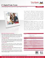
VFD820-70
Brand: ViewSonic Pages: 1

00095294 97SLP
Brand: Hama Pages: 288

M1104
Brand: Axis Pages: 56

STC-SBA503POE
Brand: Omron Pages: 59

GNOSIS
Brand: DZOFILM Pages: 24

PerfectView LCD250
Brand: Waeco Pages: 184

NCP-DVRGPSWIFI
Brand: NanoCam Plus Pages: 48
5.1 Megapixels Digital Camera
Brand: Polaroid Pages: 84

RC8221V2
Brand: Sercomm Pages: 121

NRC-80DLM
Brand: NESA Pages: 8

DF1002
Brand: iDeaPLAY Pages: 14

NB8
Brand: Observint Pages: 5

ZX-50
Brand: Pentax Pages: 104

MDC500GW
Brand: Motorola Pages: 125

MBP701
Brand: Motorola Pages: 32

MDC400
Brand: Motorola Pages: 33

MDC85
Brand: Motorola Pages: 52

xiQ series
Brand: XIMEA Pages: 109


