Blue Seal Evolution G512, Operation Manual
The Blue Seal Evolution G512 is an advanced kitchen appliance designed to elevate your culinary experience. To explore its full potential, simply head to our website to download the free user manual. This comprehensive operation manual provides detailed instructions and insights to enhance your cooking skills.
Share
Download


Reviews:
No comments
Related manuals for Evolution G512
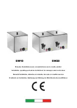
SW10
Brand: Gastrodomus Pages: 12

OCGG64COM
Brand: Omega Pages: 16

Mista Aesthetic B61GMXI9
Brand: Smeg Pages: 44

MKHG 6031-PR TC BK
Brand: MASTER KITCHEN Pages: 48

STO52
Brand: weasy Pages: 45

318200659
Brand: White-Westinghouse Pages: 12

RA 100
Brand: Rizzoli Pages: 132

DED10100
Brand: Victor Pages: 5

HP-02S.015A
Brand: HAEGER Pages: 32

PSC600D
Brand: Premium Pages: 17

VP-8 WA
Brand: Orava Pages: 16

X906 DUAL
Brand: Bertazzoni Pages: 20

W36IND MFE
Brand: Bertazzoni Pages: 16

TU64C61DX
Brand: Bertazzoni Pages: 24

BGG-889
Brand: BOLINGBAO Pages: 16

NZ36R5330R Series
Brand: Samsung Pages: 84

PU106
Brand: Smeg Pages: 11

PU106
Brand: Smeg Pages: 15


