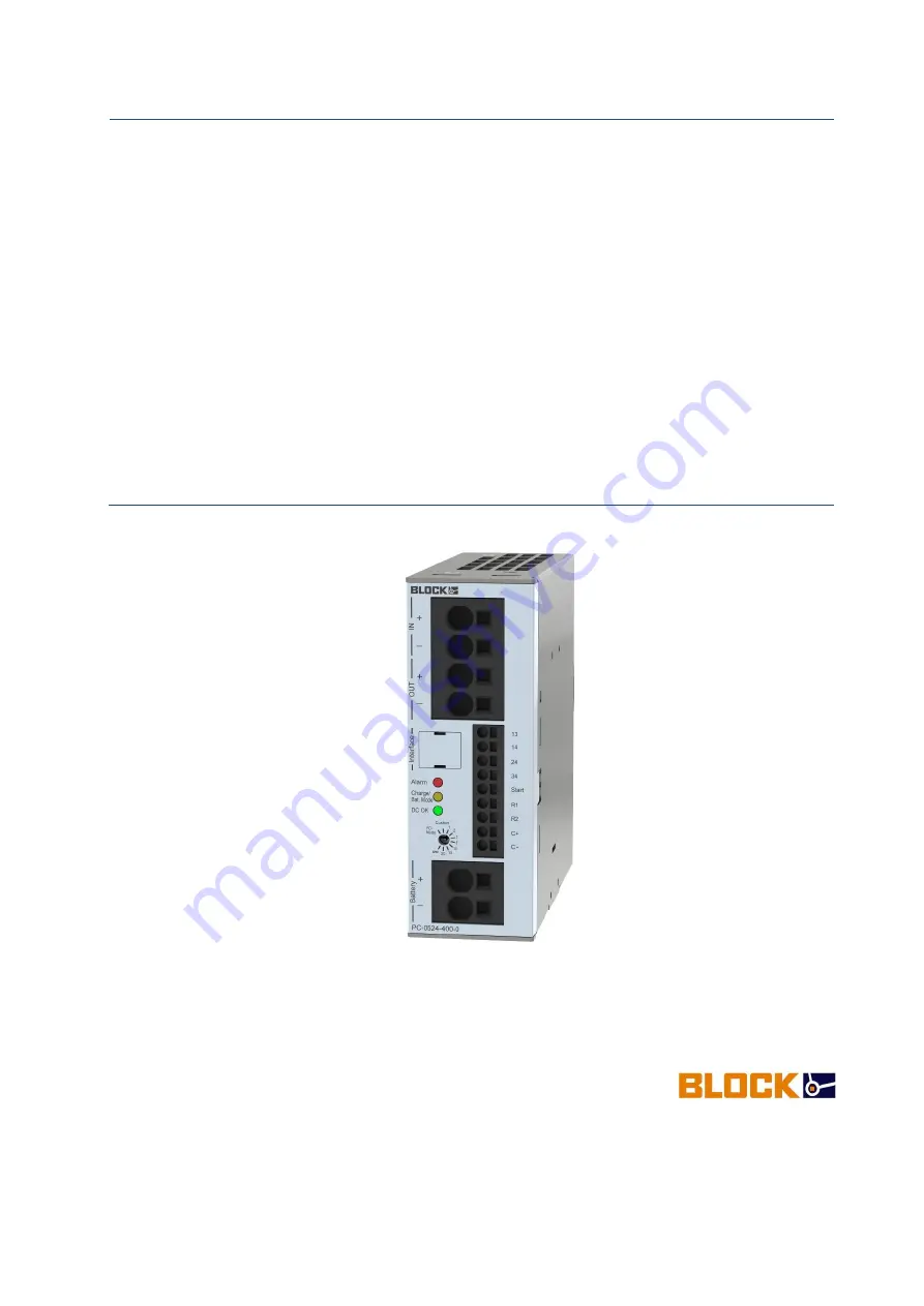
background image


Manual 


Uninterruptible 

Power Supply 


Charge and control unit 

PC-0524-400-0


BLOCK Transformatoren-Elektronik GmbH 

Max-Planck-Strasse 36–46 • 27283 Verden • Germany 

Phone +49 4231 678-0 • Fax +49 4231 678-177 

[email protected] • block.eu


Summary of Contents for PC-0524-400-0

Page 1: ...interruptible Power Supply Charge and control unit PC 0524 400 0 BLOCK Transformatoren Elektronik GmbH Max Planck Strasse 36 46 27283 Verden Germany Phone 49 4231 678 0 Fax 49 4231 678 177 info block eu block eu ...

Page 2: ...Safety Instructions 3 2 2 Qualified Personnel 3 2 3 Intended Use 3 2 4 Disclaimer 3 3 Product Description 4 3 1 Block Circuit Diagram 5 3 2 Dimensions 6 3 3 Assembly 7 3 4 Connections and Signaling 9 4 Initialization 10 4 1 Operating Statuses Signaling 10 4 2 Battery tests 14 4 3 Battery charging 15 4 4 Battery operation 17 4 5 Battery module buffer times 20 4 6 Derating 21 5 Maintenance 22 5 1 Op...

Page 3: ...00 0 24 Vdc 40 A Battery modules Variant Input voltage Rated output current Rated capacity PVAF 24 0 8 Ah 24 Vdc max 5 A 0 8 Ah PVAF 24 1 2 Ah 24 Vdc max 7 5 A 1 2 Ah PVAF 24 7 Ah 24 Vdc max 40 A 7 Ah PVAF 24 12 Ah 24 Vdc max 40 A 12 Ah PVA 24 3 2 Ah 24 Vdc max 20 A 3 2 Ah PVA 24 7 Ah 24 Vdc max 40 A 7 Ah PVA 24 12 Ah 24 Vdc max 40 A 12 Ah PBAT 1224 025 0 24 Vdc max 20 A 2 5 Ah PBAT 1224 130 0 24 ...

Page 4: ...to consideration especially the safety and warn ing information contained therein Based on their training and experience qualified personnel can guarantee that the usage of the described product satisfies all the safety requirements and applicable provisions specifications norms and laws 2 3 Intended Use This device was designed to be installed in an enclosure and is suitable for usage with genera...

Page 5: ... 12 V and 24 V grids The charge and control unit guarantees a reliable supply for industrial PCs The intelligent battery management of the UPS combines short charging times with optimized charging management for the longest possible operating life of the battery modules In addi tion ongoing monitoring of the battery modules is provided which warns users when the remaining operating life of the bat...

Page 6: ...ation between the battery module and the charge and control unit the chosen interfaces control and signal lines should be 3 meters In addition ensure that the control line is not routed parallel to the power cables otherwise there is a likelihood of communication disruptions Illustration 2 Block circuit diagram of wiring To achieve the maximum buffer time up to 3 battery modules can be installed i...

Page 7: ... 27283 Verden Germany 31 08 20 SCH Subject to technical changes 6 3 2 Dimensions The dimensions of the charge and control unit can be seen in Illustration 3 Illustration 3 Dimensions of the charge and control unit The dimensioning for the associated battery modules can be found in the operating instruc tions for the battery modules ...

Page 8: ...le rail Ensure that the device is pushed down until the stop limit When the device is on the profile rail press the underside against the mounting rail until it engages with the catch on the profile rail you will hear a click sound To check gently shake the device to ensure that it is properly locked into place A standard tool like a flat head screwdriver is needed for disassembly Press down on th...

Page 9: ...many 31 08 20 SCH Subject to technical changes 8 To ensure cooling through natural convection a distance of at least 40 mm from neighboring devices must be maintained Direct side mounting of other devices is not permitted Illustration 5 Convection cooling Attention Install the device horizontally only A different manner of mounting is not permitted ...

Page 10: ...ection USB Type B 4 Signal lights LED red Alarm LED yellow Bat Charge Bat Mode LED green DC OK 5 Rotary switch for setting the buffer period Buffer period in minutes 1 20 IPC Mode PC Mode Maximum time Custom time 6 Signal and indicating contacts 13 Potential free common input for signal outputs 14 24 34 14 Alarm default active low 24 Battery Mode default active high 34 Battery Charge default activ...

Page 11: ...es to be optimally supplied operation with connected control lines and battery modules with Battery Control is recommended Attention should be paid to the polarity Before the module is supplied with power the battery modules should be completely con nected in order to prevent false signaling 4 1 Operating Statuses Signaling The charge and control unit can signal current operating statuses warnings...

Page 12: ...break before the next start attempt Fuse Mode The output cannot be powered up within 5 seconds due to a short circuit or continuous over load The output remains switched off To end Fuse Mode the Reset Fuse Mode button must be actuated This button appears in the UPS Control Software in the Overload Behavior area as soon as Fuse Mode is enabled If the restart is unsuccessful the next attempt can onl...

Page 13: ... normal operation no battery operation possible Presence test negative or remote shut down R1 R2 active on off on UPS is in normal operation Battery replacement recommended on off flashing 1 Hz UPS is in Buffer mode IPC Mode Battery voltage 20 4 V on flashing 1Hz off flashing 1 HZ battery replacement recom mended UPS is in Buffer mode IPC Mode Battery voltage 20 4 V Device is about to switch off o...

Page 14: ...passes the wait time in Shutdown Mode is extended to 120 seconds Buffer mode is stopped buffer time has expired or buffer mode is stopped due to deep dis charge protection and the mains voltage is not in the rated range The red LED signals this status for another 5 seconds after which the system is switched off Startup from the battery If the unit must be started up externally without connecting t...

Page 15: ...tery module function ality of the accumulators and an intact fuse The presence test is performed in Normal Mode with a charging current of 1 A every 30 seconds and with a charging current of 1 A every 180 seconds In the event of a negative result the test is performed cyclically every 15 seconds If the result of the presence test is negative the Buffer mode is not possible malfunction is signaled ...

Page 16: ...rs is thereby sustainably extended Setting additional charging parame ters is not necessary due to automatic detection An IU charging characteristic is the basis for charge regulation This is a 2 level charging process as depicted below Illustration 6 Charging characteristic Level Name Description 1 Main charge Constant current charging phase of initial charging current 2 Equalization charge maint...

Page 17: ...ry default charging setting After the battery modules are detected with Battery Control the following factory default charging settings are assumed Battery modules without Battery Control are charged in factory default settings with a voltage of 27 4 V 13 7 V in 24 V 12 V operation and a charging current of 0 8 A Chart 5 Factory default charging setting Version Charging voltage Charging current PV...

Page 18: ...interruption The charge and control unit will then be in buffer mode The switch on threshold is pre configured to 22 V in the factory default settings The switch on threshold can be changed via the UPS Control configuration software 21 V 26 V adjustable 24 V operation 10 5 V 13 V adjustable 12 V operation Buffer mode with adjustable buffer time In the default factory settings the module is pre con...

Page 19: ...apsed the Bat Mode signal output is enabled This signal output remains activated during the entire configured time period In this way the IPC receives the prompt to power down During the entire configured time the IPC continues to be supplied with energy by the charge and control unit 0 65 535 seconds adjustable Idle time After the end of the switch off time the output voltage is switched off as l...

Page 20: ...s mal function is linked with the Alarm signal output so that the contact opens Deep discharge protection in buffer mode In order to protect the installed battery module against deep discharge the buffer mode is forcibly ended at a battery voltage Ubat 18 V 19 2 V 9 V 9 6 V configurable deep dis charge threshold in 24 V 12 V operation The module switches the output off The signaling with flashing ...

Page 21: ...times symbolize typical average values that result after complete charging of bat tery modules in new condition Illustration 9 Battery module buffer times The buffer time can be extended by adding up to three parallel connected battery modules In this case note that only the same battery modules with the same charge level can be connected Illustration 10 Buffer time depending on the load current A...

Page 22: ... charge and control unit it should be powered down at temperatures higher than 60 C in order to prevent overheating of the device The maximum output current is provided up to a temperature of 60 C In addition the output rated current must be lowered by 2 5 per Kelvin Illustration 11 Temperature behavior of the output rated current The maximum charging current is provided up to a temperature of 50 ...

Page 23: ...s at 20 C to 4 years at 40 C The remaining operating life is dynamically calculated depending on the ambient temperature of the battery module as long as both control lines are connected between the charge and control unit and the battery module In addition the battery modules are cyclically loaded in order to detect exceedance of a permitted voltage drop In this way conclusions can be drawn about...

Reviews: