bintec elmeg elmeg hybird 300, Installation Manual
The bintec elmeg elmeg hybrid 300 is a powerful telecommunications device that seamlessly combines multiple communication technologies. To ensure a smooth installation process, we offer a detailed Installation Manual for free download on our website. Explore the product's advanced features and capabilities by downloading the manual from manualshive.com.
Share
Download


Reviews:
No comments
Related manuals for elmeg hybird 300

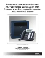
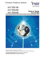
KX-TDE100
Brand: Panasonic Pages: 32
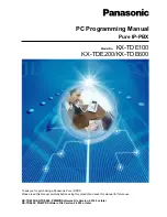
KX-TDE100
Brand: Panasonic Pages: 29
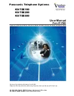
KX-TDE100
Brand: Panasonic Pages: 982
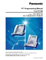
KX-TDE100
Brand: Panasonic Pages: 254
KX-TDE100
Brand: Panasonic Pages: 62
KX-TDE100
Brand: Panasonic Pages: 460

200
Brand: SARK Pages: 6

KX-TDE200
Brand: Panasonic Pages: 204

AastraLink RP 540
Brand: Aastra Pages: 16


