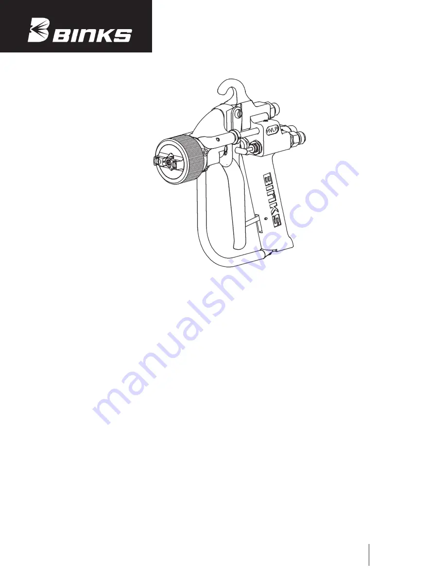
background image

Binks Model 202-755 

HVLP GUN ASSEMBLY

Replaces 

Part Sheet 

77-2756R-1  

Part 

Sheet

77-2756R-2

READ BEFORE OPERATING

Your new High Volume, Low Pressure (HVLP) Spray gun 
complies with the strict California South Coast Air Quality
Management District Rule #1162 along with Air Quality Rules
in other geographical areas. You should also know that the defi-
nition of H.V.L.P., as defined in the S.C.A.Q.M.D. Rule #1162
reads, ”High Volume Low Pressure (HVLP) spray is a coating
application system which is operated at air pressure of between
0.1 and 10 pounds per square inch gauge (PSIG).”

To maintain compliance and best results, we suggest:

1. Install air pressure test gauge (207-11799) with adapter in

gun nozzle body.

2. With an air hose connected to the assist air connection on rear

of gun, set assist air pressure to a maximum of 40 psi. Because
of the superb flow characteristics of the gun design, 40 psi
max is all that is ever required with only few exceptions.

3. Open pattern control thumbwheel all the way. Pull trigger

and observe the pressure reading of the test gauge. It should
not exceed 10 psi. Should the test gauge indicate more or
less than 10 psi, increase or decrease regulated air supply
until 10 psi is shown on test gauge while pulling trigger.
You might want to put a “landmark” on your air control
gauge for easy reference. The variables of air hose length
and regulator and gauge types sometimes require that these
adjustments become necessary.

4. Remove test gauge and adapter and install 1/16

NPT pipe

plug furnished. You are now in compliance for the criteria
HVLP. Should your local Air Quality Officer or Inspector
ever request air pressure reading, co-operate and install test
gauge and demonstrate that your nozzle pressure is 10 psi
or less.

The material transfer efficiency of your 755 HVLP  Gun is
excellent but resin and catalyst pressure(s) must also be correctly
set for optimum results.

We suggest:

1. Resin pump pressure should be set as low as possible for an

acceptable spray pattern. Remember the assist air (10 psi)
plays a big part in the final spray pattern shape.

2. Select the proper spray tip for the job. A spray tip with too

small an orifice with excessive resin pump pressure would
result in poor results. It is recommended that a range of
spray tip sizes be on hand to avoid compromises. Your
spray pattern should be a soft, uniform shape without fin-
gers or tails. Resin “bounce back” should not occur.

Catalyst and catalyst atomizing pressures should also be set as
low as possible. Usually, the Catalyst Tank pressure is set at
35-40 psi. Catalyst Fan pressure should be 10 psi lower or
25-30 psi. Flowmeter (black ball) should be adjusted for
desired gel time. A good place to start would be a black ball
reading of between 60-80. Always test spray gun and gel times
on waste material until you’re ready to fabricate parts.

OPERATING INSTRUCTIONS

Summary of Contents for 202-755

Page 1: ...ariables of air hose length and regulator and gauge types sometimes require that these adjustments become necessary 4 Remove test gauge and adapter and install 1 16 NPT pipe plug furnished You are now in compliance for the criteria HVLP Should your local Air Quality Officer or Inspector ever request air pressure reading co operate and install test gauge and demonstrate that your nozzle pressure is...

Page 2: ...HAZARD Improper equipment grounding poor ventilation open flame or sparks can cause hazardous conditions and result in fire or explosion and serious injury PINCH POINT HAZARD Moving parts can crush and cut Pinch points are basically any areas where there are moving parts KNOW WHERE AND HOW TO SHUT OFF THE EQUIPMENT IN CASE OF AN EMERGENCY PRESSURE RELIEF PROCEDURE Always follow the pressure relief...

Page 3: ...If you are now using a Halogenated Hydrocarbon Solvent in a pressurized fluid system with aluminum components or galvanized wetted parts the following steps should be taken immediately 1 Remove all pressure drain and disconnect the entire system 2 Inspect and replace all corroded parts 3 Contact your solvent supplier for a NON HALOGENATED SOLVENT to flush and clean the system of all residues HALOG...

Page 4: ... 13 71 28 DM NIPPLE 1 14 237 68 O RING 1 15 207 11258 MATERIAL FEED TUBE 1 4 1 ITEM PART NO NO DESCRIPTION QTY 21 207 10548 VALVE ASSEMBLY 1 22 237 12 ROLL PIN 1 23 207 10108 SAFETY SPRING 1 24 207 10109 SAFETY PAD 1 25 207 10107 SAFETY PIN 1 ITEM PART NO NO DESCRIPTION QTY Items are included in Repair Kit 207 11796 Please order separately PARTS LIST When ordering please specify Part No CONTINUED ...

Page 5: ...ON QTY 30 207 10192 RESIN NEEDLE COLLET 1 31 207 10191 RESIN NEEDLE HOLDER 1 32 207 11364 MATERIAL VALVE ASSEMBLY 1 33 207 10096 RESIN NEEDLE SEAT 1 34 237 152 WASHER 1 35 207 10098 TRIGGER GUARD STUD 1 36 207 10100 1 TRIGGER GUARD 1 37 237 212 PAN HEAD SCREW 1 38 207 11340 SHUT DOWN PLUG NOT SHOWN 1 39 207 11796 REPAIR KIT NOT SHOWN 1 40 207 11799 TEST GAUGE KIT 1 41 237 707 WET FILM GAUGE 1 Also...

Page 6: ... 3236 O RING 1 9f 207 12141 PUSHROD 1 9g 207 11329 SPRING 1 Items are included in Repair Kit 207 11796 Please order separately ITEM PART NO NO DESCRIPTION QTY PARTS LIST When ordering please specify Part No ITEM 9 ON MAIN EXPLODED VIEW 9g 9f 9e 9d 9c 9b 9a 207 10548 VALVE ASSEMBLY 21a 207 10252 VALVE CAP 1 21b 20 3562 O RING 2 21c 207 10286 SPACER 1 21d 207 10088 VALVE BODY 1 21e 237 92 O RING 1 2...

Page 7: ...IP SELECTION CHART 207 11796 REPAIR KIT 32a 207 11345 RESIN NEEDLE 1 32b 207 11330 SPRING 1 32c 237 69 O RING 1 32d 207 10093 NEEDLE FITTING 1 32e 207 10095 NEEDLE PACKING 1 32f 207 10094 PACKING NUT 1 Items are included in Repair Kit 207 11796 Please order separately 2b 237 708 O RING 1 2c 237 709 O RING 1 4 237 89 O RING 3 5 207 11392 SEAL 1 7 20 2198 O RING 2 9d 207 11547 SEAL 2 9e 20 3236 O RI...

Page 8: ...age Clean assembly and replace in valve assembly holds needle open packing Lubricate Material leaks at back of Packing nut too loose Tighten packing nut slightly material valve Packing worn Clean assembly and replace packing No material when trigger Out of material Check supply is pulled Pump filter clogged Clean filter Pump by pass valve open Close valve Plugged tip Remove and clean carefully wit...

Reviews: