background image

Service Instructions 

VCIOM-15313-EN Rev. 1 

March 2022

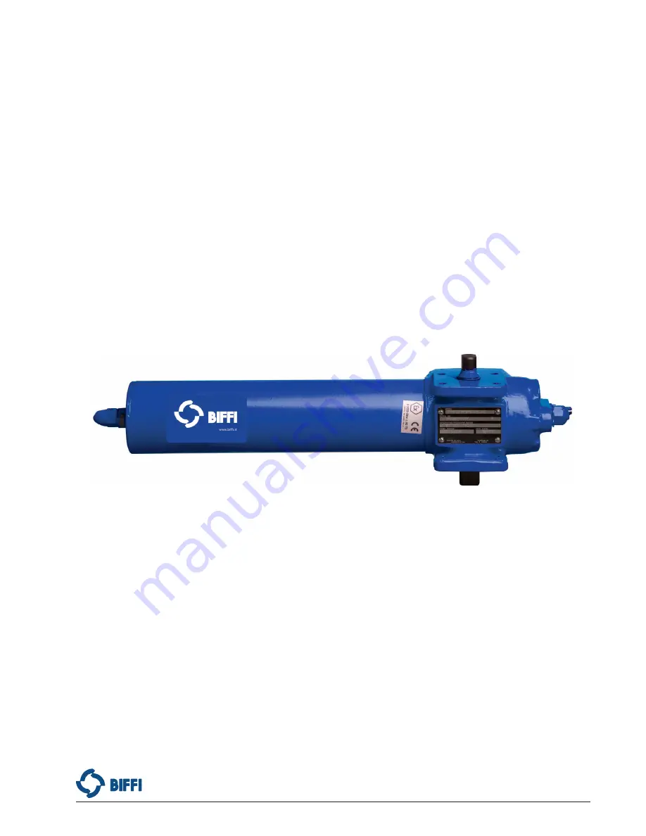
FCB Series Pneumatic Actuators

Model FCBB Spring-Return Dissasembly and Reassembly

Copyright © Biffi. The information in this document is subject to change without notice. Updated data sheets can be obtained from our website www.biffi.it or from your nearest Biffi Center: 


Biffi Italia s.r.l. - Strada Biffi 165, 29017 Fiorenzuola d'Arda (PC) –

 Italy PH: 

+39 0523 944 411 – [email protected]

Summary of Contents for FCB Series

Page 1: ...mbly and Reassembly Copyright Biffi The information in this document is subject to change without notice Updated data sheets can be obtained from our website www biffi it or from your nearest Biffi Center Biffi Italia s r l Strada Biffi 165 29017 Fiorenzuola d Arda PC Italy PH 39 0523 944 411 biffi_italia biffi it ...

Page 2: ...This page intentionally left blank Notes March 2022 Service Instructions VCIOM 15313 EN Rev 1 ...

Page 3: ...up 5 1 12 Actuator Operation 6 Section 2 Actuator Disassembly 2 1 General Disassembly 7 2 2 Spring Cylinder Disassembly 8 2 3 Housing Disassembly 10 Section 3 Actuator Reassembly 3 1 General Reassembly 11 3 2 Housing Reassembly 11 3 3 Spring Cylinder Reassembly 14 Section 4 Actuator Testing 4 1 Actuator Testing 17 4 2 Return to Service 18 4 3 Pressure Requirement and Limitations for FCBB SR Actuat...

Page 4: ...This page intentionally left blank Notes March 2022 Service Instructions VCIOM 15313 EN Rev 1 ...

Page 5: ...procedure 1 1 2 Normal recommended service interval for this actuator series is five years NOTE Storage time is counted as part of the service interval 1 1 3 This procedure is applicable with the understanding that all electrical power and pneumatic pressure have been removed from the actuator 1 1 4 Remove all piping and mounted accessories that will interfere with the module s that are to be work...

Page 6: ...r jackscrew assembly ES Extended Stop s 1 3 General Safety Information 1 3 1 Products supplied by Biffi in its as shipped condition are intrinsically safe if the instructions contained within this Service Instruction are strictly adhered to and executed by well trained equipped prepared and competent personnel WARNING For the protection of personnel working on Biffi actuators this procedure should...

Page 7: ...used without prior written approval of Biffi Product Engineering The lubricant item number on some assembly drawings is item 5 while the Biffi service kits lubricant item number is item number 500 1 6 2 Standard and high temperature services 20 F to 350 F 29 C to 176 C use Biffi ESL 5 lubricant ESL 5 lubricant is contained in the Biffi Module Service Kit in tubes or cans and they are marked ESL 5 ...

Page 8: ...storage if available is recommended for all actuators Care should be taken to plug all open ports on actuator and controls to keep out foreign particles and moisture Also actuators should not be stored in an atmosphere harmful to resilient seals For extended storage contact the factory 1 10 Actuator Installation 1 10 1 Since there are many valve and actuator combinations it is not practical to inc...

Page 9: ...itching valves in normal operating position as per Schematic Instructions 1 11 2 Check Connections a Pneumatic hydraulic components connected as per schematic enclosed or in service manual supplied b Pneumatic supply connected to identified ports c Electrical connections terminals are secure d Wiring as per enclosed diagram or service manual supplied 1 11 3 When actuator is first put into service ...

Page 10: ...sure of actuator or control components slower operating times may be obtained using flow control valves to meter the exhaust Excessive exhaust flow metering may cause erratic operation Normally incoming supply should not be metered 1 12 Actuator Operation 1 12 1 Controlled Operation Controlled operation is accomplished by pressurizing and or depressurizing the appropriate cylinder inlet s of a dou...

Page 11: ...e actuator name tag NOTE Before starting the general disassembly of the actuator it is a good practice to operate actuator with the pressure used by the customer to operate the actuator during normal operation Notate and record any abnormal symptoms such as jerky or erratic operation 2 1 1 Remove all operating pressure from actuator allowing the spring to stroke The spring will rotate the yoke to ...

Page 12: ... 80 and washer 2 35 from stop screw 1 70 located in housing 1 10 2 2 1 1 2 Remove stop screw 1 70 located in housing 1 10 2 2 1 2 For FCBB315 420 520 525 725 SR M3 or M3HW 2 2 1 2 1 Remove retainer ring 12 30 and groove pin 12 20 from optional hex drive hub or from hand wheel 12 10 2 2 1 2 2 Remove optional hex drive hub or handwheel 12 10 from M3 jackscrew 1 70 2 2 1 2 3 Loosen and remove hex nut...

Page 13: ...nue to rotate center bar assembly 8 10 counter clockwise CCW until the spring preload is eliminated As preload is reduced it may be necessary to keep end cap 4 20 from turning 2 2 8 After the spring preload is eliminated unscrew and remove end cap 4 20 from center bar assembly 8 10 2 2 9 Remove spring 4 70 from within spring cylinder 4 10 2 2 10 Hold torque shaft 1 30 and pull spring cylinder 4 10...

Page 14: ... 30 it should be removed 2 3 4 Remove the torque shaft 1 30 by pushing it out one side of housing 1 10 2 3 5 Remove yoke key 1 40 and yoke key spring 1 50 from torque shaft 1 30 2 3 6 Remove yoke 1 20 from housing 1 10 2 3 7 For actuator models FCBB315 SR with a M3 or M3HW mounted in the outboard end of housing 1 10 remove M3 jackscrew 1 70 from housing 1 10 NOTE The M3 jackscrew 1 70 will be remo...

Page 15: ...ngs beneath the washers on the housing These items MUST be replaced upon reassembly NOTE Coat the torque shaft O ring 2 25 with grease upon installation The following steps used to reassemble the following models FCBB315 420 520 525 and 725 Use assembly drawing part numbers 152230 and 152608 for this section CAUTION Actuator parts that reflect any of the above listed characteristics may need repla...

Page 16: ...TION FOR FCBB420 520 525 725 SR M3 3 2 2 1 Apply a coating of lubricant to outer diameter and inner diameter threads of M3 adapter 1 90 3 2 2 2 Coat O ring seal 2 45 with lubricant and install into outer diameter seal groove located in the M3 adapter 1 90 3 2 2 3 Apply a light coating of lubricant to the threads of M3 jackscrew 1 70 3 2 2 4 Install and rotate the M3 jackscrew 1 70 into M3 adapter ...

Page 17: ... assembly drawing for correct yoke key spring and yoke key orientation 3 2 7 Hold the yoke key 1 40 down with your thumb insert the torque shaft 1 30 by gently rotating it into the housing 1 10 and yoke 1 20 on the opposite side of the installed torque shaft wiper seal 2 20 NOTE Torque Shaft should be installed with the key rotated 180 opposite yoke key slot When the torque shaft 1 30 is flush wit...

Page 18: ...er adapter 4 15 facing away from housing 1 10 3 2 15 2 Install one O ring seal 5 15 onto stepped diameter of cylinder adapter 4 15 3 3 Spring Cylinder Reassembly 3 3 1 Coat piston 4 50 outer diameter seal groove inner diameter seal groove head of piston and exposed ends of yoke pin with lubricant 3 3 2 Coat O ring seal 5 20 with lubricant and install in the internal seal groove in the head of pist...

Page 19: ...oximated setting recorded in Section 2 step 2 1 2 NOTE Position spring cylinder 4 10 so that spring tag 4 60 will be adjacent to accessory mounting pads located on the actuator housing 3 3 13 Install end cap 4 20 onto center bar assembly 8 10 by rotating the end cap in a clockwise direction 3 3 14 Position the end cap 4 20 so that the breather port is at the bottom and the stop screw ES 4 30 is at...

Page 20: ...to stop screw 1 70 until it is hand tight 3 3 21 4 For FCBBXXX SR modles install hex nut 4 40 and washer 1 90 onto stop screw 1 70 until hand tight 3 3 21 5 Install hex nut 1 80 onto stop screw 1 70 until it is hand tight 3 3 22 Install O ring seal 5 30 onto the stop screw ES 4 30 until it is flush with the end cap 3 3 23 Install new washer 4 90 onto the stop screw ES 4 30 until it is close to the...

Page 21: ...als to seek their service condition 4 1 5 Apply the pressure listed in step 4 1 3 to the housing side of the piston and allow the actuator to stabilize 4 1 6 Apply a leak testing solution to the following areas 4 1 6 1 Spring cylinder to housing joint on FCBB315 SR FCBB420 SR and FCBB525 SR or spring cylinder to cylinder adapter to housing joints on FCBB415 SR FCBB520 SR and FCBB725 SR actuators 4...

Page 22: ...For models with BREATHER 10 COLD TEMP do the following 4 2 2 1 Install breather 30 10 elbow 30 30 and hex nipple 30 20 into end cap 4 20 4 2 3 After the actuator is installed back on the valve all accessories should be hooked up and tested for proper operation and then replaced if found defective 4 3 Pressure Requirement and Limitations for FCBB SR Actuators Table 4 Pressure Requirement and Limita...

Page 23: ... maintenance Disassemble cylinder assembly to remove debris Reassemble cylinder assembly as necessary Defective valve Consult the valve manufacturer s documentation Apparent lack of torque Inadequate supply pressure Ensure supply pressure is above the minimum operating pressure of the actuator and that output torque produced at supply pressure exceeds valve torque demand Incorrect speed control se...

Page 24: ...tor valve 5 2 1 1 3 Upon successful completion of the above described Full Stroke Test procedure the Test Coverage can be considered 99 5 2 2 Partial Stroke Test when requested The Partial Stroke Test On line can be performed to improve the PFDAVG value and to satisfy PFDAVG average probability of failure on demand value A typical partial stroke value is 15 of the stroke and the recommended test i...

Page 25: ...l pressure first including storage tank if present Next bleed off pilot pressure and disconnect pneumatic pressure supply pilot tubing and electrical wiring if equipped Before starting the disassembly a large area should be created around the actuator as to allow any kind of movement Separate the parts comprising the actuator according to their nature e g metallic plastic materials fluids etc and ...

Page 26: ...3 EN Rev 1 22 List of Tables List of Tables List of Tables Table 1 FCBB SR Model Numbers 1 Table 2 Actuator Weight 4 Table 3 Tightening Torque Center Bar 16 Table 4 Pressure Requirement and Limitations 18 Table 5 Symptoms and Solutions Table 19 ...

Page 27: ...Service Instructions VCIOM 15313 EN Rev 1 March 2022 23 Appendix Appendix Appendix A List of Drawings A 1 Part No VA152230 D FCBBXXX Assembly Drawing ...

Page 28: ...March 2022 Service Instructions VCIOM 15313 EN Rev 1 24 Appendix Appendix A 2 VA152608 F FCBBXXX SRX M3 Assembly Drawing ...

Page 29: ...Service Instructions VCIOM 15313 EN Rev 1 Notes March 2022 This page intentionally left blank ...

Page 30: ...the products or services described herein or their use or applicability All sales are governed by our terms and conditions which are available on request We reserve the right to modify or improve the designs or specifications of our products at any time without notice For complete list of sales and manufacturing sites please visit www biffi it or contact us at biffi_italia biffi it Biffi Italia s ...

Reviews: