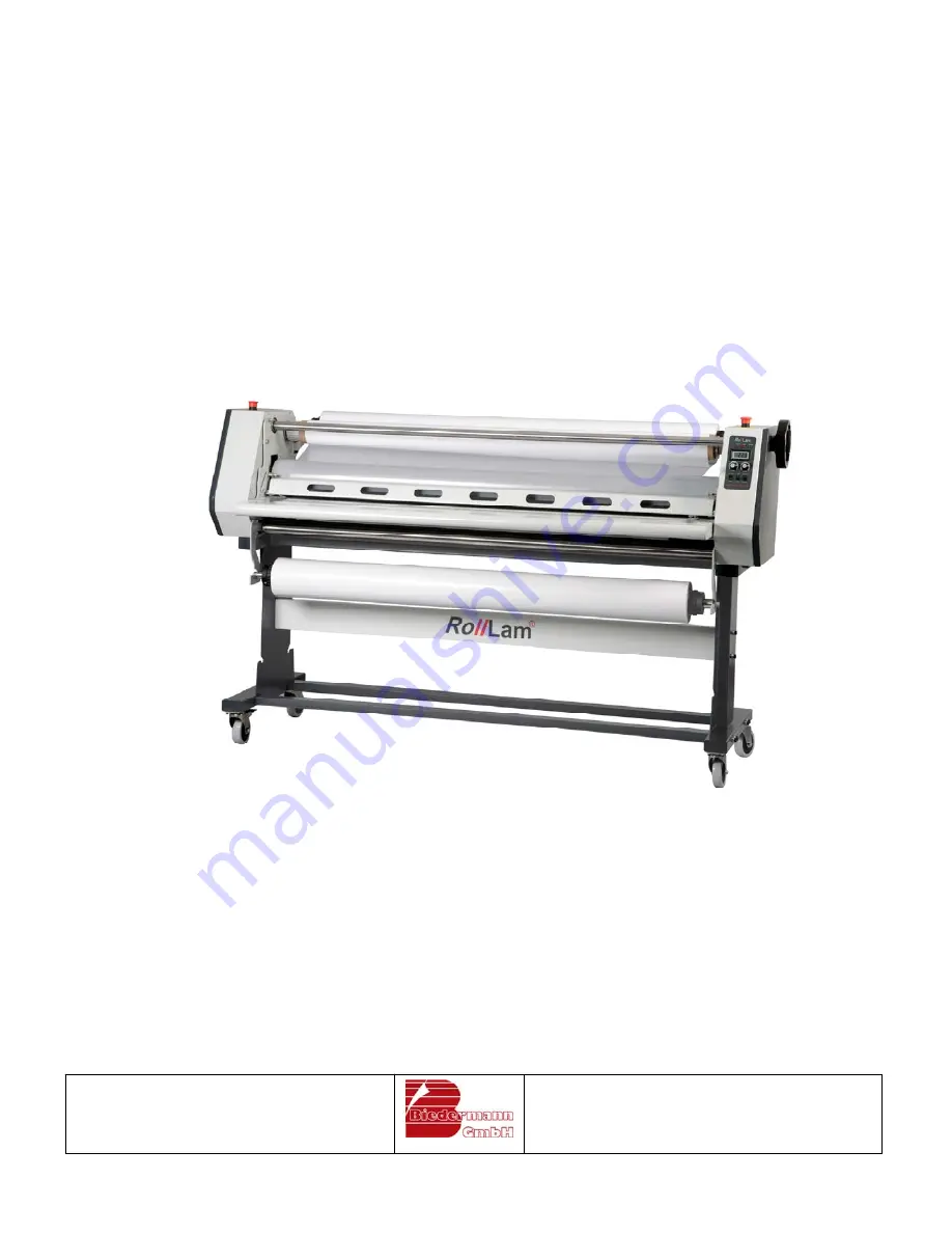
background image


  OPERATION 

MANUAL 

 
  Laminators 


RollLam 120W; RollLam 140W; RollLam 160W 


Biedermann GmbH 

Solutions for mounting and laminating 

DE-70806 Kornwestheim, Heubergstraße 19 

 Phone:+49(0)7154-83990; Fax:+49( 0)7154-839983 

 E-mail: [email protected] 

 www.biedermanngmbh.com 


Summary of Contents for RollLam 120C

Page 1: ...RollLam 120W RollLam 140W RollLam 160W Biedermann GmbH Solutions for mounting and laminating DE 70806 Kornwestheim Heubergstra e 19 Phone 49 0 7154 83990 Fax 49 0 7154 839983 E mail info biedermanngmb...

Page 2: ...ion passing on to third parties as well as any kind of duplication and publication are prohibited without prior written permission and will result in legal action in accordance with the applicable law...

Page 3: ...operating comfort were of great importance You will be satis fied with your machine for many years if you operate and maintain it properly Please become familiar with the most important elements of yo...

Page 4: ...n pre coated substrates Mounting large pictures on pre coated substrates Laminating Laminating with the aid of working boards Working with pre cut laminates Working from the roll Laminating with the a...

Page 5: ...n can cause accidents 6 ROOM CONDITIONS Do not expose the machine to rain Do not use the machine in damp or wet rooms Ensure lighting is good Do not use the machine close to flammable liquids or gas 7...

Page 6: ...the correct way round front of machine on front of stand rear of machine on rear of stand Installation of the supply shaft holders The holders for the top supply shaft 1 as well as the bottom supply s...

Page 7: ...mm Diameter of rollers 112 mm 112 mm 130 mm Max speed 3 5 m min 3 5 m min 4 m min Voltage 230V 0 9 KW 230V 1 0 KW 230V 1 3 KW Adjustment of height central central central Finger protection yes yes yes...

Page 8: ...or pressure adjustment 4 Pressure transmission shaft 5 Emergency stop switch 6 Top roller 7 Finger protection with integrated feed in roller 8 Front working table with swing out option and scale 9 Swi...

Page 9: ...m 120W RollLam 140W RollLam 160W 9 4 2 Rear view 16 Connecting cable 17 Main switch 18 Fuse for the heating element 19 Fuse for the controller 20 Connector for the take up unit at the backside 21 Rail...

Page 10: ...the emergency stop switches are switched off 2 Switch off the speed regulator 6 3 Switch on the main switch 17 4 Adjust the requested temperature and wait until the control lamp 3 starts to light 5 O...

Page 11: ...ary to switch over to Step be fore continuous working is possible again 7 Backward operation When selecting switch 8 to Reversal the backwards mode is activated By pressing the foot switch the drive r...

Page 12: ...maximal 40 degrees more ATTENTION Too much pressure can cause the occurrence of waves Picture 5 Hand wheel 5 2 Adjustment of the brakes The supply shafts are equipped with an integrated brake mecha ni...

Page 13: ...film is optimally adjusted loosen the brakes Picture 6 Quick gripping cones with inte grated brake mechanism 5 3 Quick gripping cones Besides the regulation of the tension of the film the quick gripp...

Page 14: ...t 4 and lay it loosely over the top roller 6 4 Push the film evenly in between the rollers by using the threading board so that the film is tight wrinkle free Finally feed in the substrate Due to econ...

Page 15: ...pressure to stick the picture onto the exposed adhesive Too much and irregular pressure can lead to wrinkling 5 Push the mounting board with the tacked picture manually between the rollers To guarante...

Page 16: ...ubstrate are fixed between the rollers This will avoid the picture shift ing 5 Drape the front part of the picture over the top roller 6 ADVICE If you work alone weight the draped part of the picture...

Page 17: ...out the picture from time to time along the top roller 6 Self adhesive vinyl films The sequence explained above is similar when mounting pictures already coated with adhesive for example self adhesiv...

Page 18: ...p of adhesive 4 Align the adhesive strip with the working board and fix it with a little pressure 5 Run the working board with the laminating film through the rollers by using the foot switch so that...

Page 19: ...laminating film onto the top supply shaft 1 so that the film can be pulled toward the user from the underside of the roll with the silicone release paper side facing to the bot tom 4 Pull off the lam...

Page 20: ...the brakes on the cones 10 Align the picture with the working board 11 Feed in the working board with the picture subsequent to the threading board and start with the lamination process ATTENTION Do...

Page 21: ...to the top supply shaft 1 so that the film can be pulled toward the user from the underside of the roll with the silicone release paper side facing to the bot tom 5 Pull off the laminating film incl c...

Page 22: ...s tight without wrinkles If necessary regulate the tension of the film with the aid of the brakes on the cones 11 Lower the top roller 6 until it touches the threading board Run the threading board th...

Page 23: ...ilm incl cover paper from the sup ply shaft until it can be wrapped around the core from the bot tom Fix the film incl cover paper with an adhesive strip on the core and wind up one rotation by hand A...

Page 24: ...aminating film with the silicone coating facing inwards Run the envelope between the rollers until only 2 3 cm of the envelope remain visible Push the picture in the envelope and adjust it The advanta...

Page 25: ...wrapped around the core from the bot tom Fix the film incl cover paper with an adhesive strip on the core and wind up one rotation by hand Adjust the brakes on the cones so that the film can be unwou...

Page 26: ...he cones 10 Lower the top roller 6 until it touches the threading board Run the threading board through the rollers 11 As soon as the threading board comes out the back of the laminator lower the top...

Page 27: ...ide of the roll with the silicone release paper side facing to the bot tom 5 Pull off the laminating film incl cover paper from the sup ply shaft until it can be wrapped around the core from the bot t...

Page 28: ...between the rollers by using the threading board so that the films are tight without wrin kles If necessary regulate the tension of the films with the aid of the brakes on the cones 12 Lower the top r...

Page 29: ...t must be equipped with a core and winds up the pic tures directly after the lamination process Picture 10 Take up unit rear side 6 5 3 Media holder Advice When working with large pictures it is recom...

Page 30: ...ifferent widths it is possi ble to avoid a frequent change over by additional supply shafts There are three possibilities for the storage of the shafts on the stand One on the front side 14 and two at...

Page 31: ...uring the lamina tion process There is too much pressure Check the pressure see p 12 The rollers are not adjusted properly The rollers are adjusted exactly before shipment but although rare it is poss...

Page 32: ...n process Check the adjustment of the brakes and loosen them a little for the next lamination see p 13 The picture is fed in crook edly The picture has not been fed in at an angle of 90 degrees to the...

Page 33: ...ubstrate three work steps What comes first Mounting or laminating Generally it is recommended to laminate the picture first and afterwards mount it on a substrate When laminating already mounted pictu...

Reviews: