USER’S MANUAL
Carefully read entire manual before operating
the log splitter!
Südharzer Maschinenbau
GmbH
Helmestraße 94 ∙ 99734 Nordhausen/Harz
Zentrale:
+
49(0)3631/6297-0 ∙
-111
Internet: www.bgu-maschinen.de
e-mail: [email protected]
- Set-up
- Use
- Maintenance
- Accessories
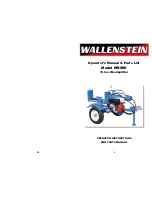
UNIVERSAL LOG
SPLITTER
MODELS
USP 13 - 6, USP 16 - 2, USP 22-2
We manufactu-
re in Germany