background image

BEST ACCESS SYSTEMS

A Division of Stanley Security Solutions, Inc

T81600 Rev A    1919380    ER-7991-12   July 2006

1

Overview

Contents

The 34HM–35HM IDH Max Mortise Lock provides the fol-
lowing features in an integrated lock, eliminating the 
need to install separate sensors in and around the door 
frame:

electrified locking mechanism

electronic token reader

integrated trim

door status detection

latchbolt status detection

ability to exit without triggering an alarm

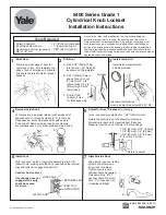
The figure below shows the relationship between the 
components in the IDH Max system.

These installation instructions describe how to install, 
wire, and configure the components provided with your 
34HM–35HM IDH Max Mortise Lock. The following topics 
are covered.

Site survey

................................................................ 2

Components checklist

............................................. 2

Special tools checklist

............................................. 3

Preparing the door and door jamb

........................ 4

Installing the lock

.................................................... 8

Completing the installation at the door

.............. 15

Testing the installation

......................................... 19

Troubleshooting the installation

......................... 20

Installation Instructions for
IDH Max 1300 Mortise Locks

Power
supply

Lock

Wire
transfer
hinge

Field wire 

harness

Power (2)

RS-485 Communication (2)

B.A.S.I.S.  
or  
Lenel  
Access  
Control  
Panel

Summary of Contents for IDH Max 1300

Page 1: ...igure below shows the relationship between the components in the IDH Max system These installation instructions describe how to install wire and configure the components provided with your 34HM 35HM IDH Max Mortise Lock The following topics are covered Site survey 2 Components checklist 2 Special tools checklist 3 Preparing the door and door jamb 4 Installing the lock 8 Completing the installation...

Page 2: ...ts for ANSI BHMA 156 25 Side of door Range Inside 66 F to 74 F 19 C to 23 C Outside 31 F to 151 F 35 C to 66 C Side of door Range Inside and out side 32 F to 120 F 0 C to 49 C Use the following checklist to make sure that you have the items necessary to install the components provided with your 34HM 35HM IDH Max Mortise Lock Components provided in the box Mortise case assembly Mortise case facepla...

Page 3: ...ming The distance from the power supply to the first door If powering more than one door daisy chained to the same power supply add the total distance of the power runs between the doors Refer to the table below to determine the minimum wire gauge based on the number of doors sharing the power supply and the total length of the wire run Field wiring for RS 485 communication connections between the...

Page 4: ...outside of the door 2 On the door s edge and door jamb mark the vertical centerline of the lock 3 Measure and mark the backset 2 3 4 standard from the vertical centerline on the door s edge On both sides of the door mark the vertical centerline of the lock 4 On the door jamb mark the horizontal centerline of the strike 3 8 above the horizontal centerline of the lock 2 Position template and mark dr...

Page 5: ...se for lock case and faceplate 1 Mortise the edge of the door for the lock case Note The mortise cavity depth of 4 5 8 includes clear ance for wiring behind the mortise case 2 Insert the lock in the mortise cavity 3 Mark the outline of the lock faceplate 4 Remove the lock Mortise to fit the faceplate Figure 3 Mortising for the lock case and faceplate Door Lock faceplate mortise Lockcase mortise Lo...

Page 6: ... through door sensor solenoid wire hole 7 8 diameter from inside into mortise cavity approximately 1 deep Note 1 To locate the center of a hole on the opposite side of the door drill a pilot hole completely through the door Note 2 For holes through the door it is best to drill half way from each side of the door to prevent the door from splintering Figure 4a Drilling the RH and RHRB holes Outside ...

Page 7: ...field wiring 1 Drill a wire access hole through the frame side of the hinge mortise 2 Drill holes or pockets for splice connectors in the frame and door Refer to the hinge manufacturer s specifications for the hole location 3 De burr the holes to prevent damage to the hinge leads 4 Run the power field wiring from the location for the lock s power supply to the location for the wire trans fer hinge...

Page 8: ... 8 Pull field wire harness through door 1 Feed the field wire harness connected to the inside trim into the field harness reader wire hole and down into the mortise cavity 2 From the hinge edge of the door fish the field wire harness through the door to the hinge mortise Note You can let the inside trim dangle from the field wire harness while completing tasks 9 through 13 Figure 7 Mortising the d...

Page 9: ...e cavity 3 Make sure there are 3 to 4 of slack in the field wire harness to allow access to the control electronics cir cuit board in the inside trim 4 Secure the mortise case with the case mounting screws 10 Install mounting plates 1 Insert the outside mounting plate through the door and mortise case 2 Position the inside mounting plate opposite the out side mounting plate and screw them securely...

Page 10: ...face Adjust the cylinder depth plus or minus one 1 turn so that the core when installed in the cylinder is flush with the outer surface of the trim Caution A malfunction can occur if the cylinder is threaded in too far 2 Secure the cylinder in the mortise case with the case set screw 3 Secure the mortise case faceplate to the mortise case with the faceplate mounting screws 4 Check the cylinder and...

Page 11: ...ert the two trim hole inserts into the upper trim hole on each side of the door as shown in Figure 12 2 Insert two bushings into the field harness reader wire hole on each side of the door as shown in Figure 12 3 Insert a bushing into the sensor solenoid wire hole on the inside of the door as shown in Figure 12 Figure 12 Installing the trim hole inserts and bushings Outside of door Trim hole inser...

Page 12: ...h the large opening in the inside trim Figure 13a Feeding the reader wire harness connector from the outside trim through the door Reader wire harness connector Field harness reader wire hole Outside trim Outside of door Figure 13b Connecting the reader wire harness to the control electronics circuit board Reader wire harness connector Sensor wires and solenoid wires Solenoid and sensor wire harne...

Page 13: ...B A S I S reader address set up in the management software See the Sys tem Administration User Guide for more information on reader addressing 1 On the inside control electronics board use the first five switches to set the reader address in binary code Switch one is the least significant digit 2 Use the table below to set both switches 6 and 7 to the baud rate at which the locks will communicate ...

Page 14: ...N ON ON 8 ON 9 ON ON 10 ON ON 11 ON ON ON 12 ON ON 13 ON ON ON 14 ON ON ON 15 ON ON ON ON 16 ON 17 ON ON 18 ON ON 19 ON ON ON 20 ON ON 21 ON ON ON 22 ON ON ON 23 ON ON ON ON 24 ON ON 25 ON ON ON 26 ON ON ON 27 ON ON ON ON 28 ON ON ON 29 ON ON ON ON 30 ON ON ON ON 31 ON ON ON ON ON 1 2 3 4 5 6 7 8 ON Figure 14 DIP switches on the Control Electronics circuit board set to reader address 5 and 38 400 ...

Page 15: ...on 3 Make the solenoid connection and three sensor con nections and place the wires into the inside trim Caution When making the sensor connections and solenoid connection make sure there are no loose wire connections where the wires are inserted into the connectors the connectors are firmly mated 16 Install inside and outside knobs levers For both knobs and levers Unscrew the inside spindle one 1...

Page 16: ...the outside of the door 2 Slide the inside lever onto the inside spindle and secure it with the set screw 3 Tighten the trim mounting screws 4 Turn the levers to check that they operate smoothly 17 Install core EEL and EEU only 1 Insert the control key into the core and rotate the key 15 degrees to the right 2 With the control key in the core insert the core into the cylinder 3 Rotate the control ...

Page 17: ...Leave sufficient length to connect to the wire transfer hinge 2 Splice the power and communication field wiring to the four pairs of leads on the frame side of the hinge following the hinge manufacturer s instructions 3 Splice the four field wire harness wires listed in the table below to the four pairs of leads on the door side of the hinge matching each pair of leads to its corre sponding field ...

Page 18: ...he door is closed If the incorrect strike is installed a lock in can occur Note The recommended gap between the door and jamb is 1 8 21 Optional Install lock power supply If you are providing a separate power supply for the lock instead of providing power via the panel inter face module connect the two power field wires run from the wire transfer hinge to the power supply Make sure power 12 volts ...

Page 19: ...ontrolpanel If youencounter problems see Troubleshooting the installation on page 20 1 Check the control electronics red status LED Both LEDs should be blinking red indicating that the communication connection between the access con trol panel and the lock s control electronics circuit board is OK 2 After performing any necessary programming for the lock and putting the door in a locked mode use a...

Page 20: ...alarm response is triggered by the access control panel indicating that the latch bolt status sensor is working Troubleshooting To troubleshoot installation problems refer to the table below For more information refer to the IDH Max Lock Service Manual T60775 and to the documentation pro vided by the manufacturer of the access control panel reader interface You notice Possible causes include You s...

Reviews: