Bell System Practices F-56593, Identification, Installation, Connections, And Maintenance
Bell System Practices F-56593 is a comprehensive manual covering the identification, installation, connections, and maintenance procedures for a wide range of telecommunications equipment. Download this invaluable resource for free from manualshive.com, to ensure smooth operations and efficient management of your telecom infrastructure.
Share
Download


Reviews:
No comments
Related manuals for F-56593

WH66 Mono
Brand: Yealink Pages: 12

WH62 Mono
Brand: Yealink Pages: 12

WH62 Mono
Brand: Yealink Pages: 8

T41
Brand: Yealink Pages: 24

Argonaut IC2
Brand: Aegisound Pages: 16

TESPORTINEARBTEVO2K
Brand: SBS Pages: 12

HS-BT102-BK
Brand: Hipstreet Pages: 3

RZ04-0346
Brand: Razer Pages: 19

Muses 801
Brand: Grandvue Pages: 14

ProBoom
Brand: Jabra Pages: 2

zoro II Wireless
Brand: Noontec Pages: 12

X5
Brand: Blueant Pages: 37
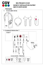
HEL PRELUDE 2 DUO
Brand: CGV Pages: 6

200
Brand: Sound ID Pages: 68

BT400 GII
Brand: Bluetake Technology Pages: 13

403US-0003
Brand: 1byone Pages: 31

SH10X
Brand: Seht Pages: 8

LifeTalks IH-H410UR
Brand: iHome Pages: 2


