INSTALLATION
WALL MOUNT - SINGLE FACE:
1. Extend unswitched 24 hour AC supply of rated voltage to junction box or appropriate wiring (supplied by others). Leave at least eight
(8) inches of slack wire. The circuit should not be energized at this time.
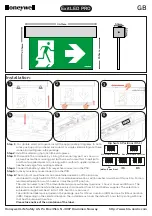
2. Open the exit sign faceplate by inserting the tip of a screwdriver into the gap between the faceplate and the exit frame, near the top of
the exit. Slowly twist the screwdriver until the faceplate releases (Figure 1).
3. Pull the hinged faceplate down and out (Figure 2).
4. Remove the exit sign universal canopy kit from inside the exit (if located there).
5. Knock out the appropriate mounting pattern and/or wire pass-thru hole on the exit back plate to fit the junction box or wiring connector
being used (supplied by others).
6. Bring wires through the back of the sign and mount the exit securely in place. Screw directly to junction box if possible.
7. Connect AC supply per diagram provided (Figure 5). Insulate unused wire!
CAUTION! - Failure to insulate unused wire may result in a shock hazard or unsafe condition as well
as equipment failure.
8. Route wires and secure them in place.
9. Remove any directional chevron arrows to be indicated as required from the exit stencil. You may have to remove the red fibre first.
10. Insure that the faceplate strike catches remain at 90°. If strikes have been deformed then the faceplate will not hold securely. Bend both
strikes back to 90° if necessary (Figure 3).
11. Replace the red exit fibre (if removed) and press the faceplate back into the exit frame until securely latched.
12. Turn on the AC voltage supply.
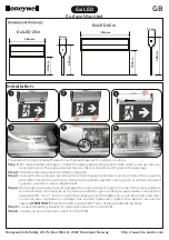
CEILING/END MOUNT - SINGLE OR DOUBLE FACE:
1. Follow steps 1 to 4 of Wall Mounting instructions above.
2. On the top and both sides of the exit there are three (3) holes for the canopy - two (2) for the mounting screws and one (1) wire pass-
thru hole. Knock out the three appropriate canopy mounting holes for your installation.
3. Secure the canopy to the exit sign using the supplied 1 inch screws and washer nuts and align the wire
pass-thru hole in the frame to the wire pass-thru hole in the centre of the canopy.
4. Bring wires through the wire pass-thru and connect AC supply as described in step 7 of Wall Mounting instructions above.
5. Secure the exit to the wall or ceiling using the supplied 1-1/2 inch screws and nuts. Screw directly to junction box if possible. A univer-
sal spider plate is supplied to allow for exit sign placement adjustment or connection to a variety of electrical boxes (Figure 4).
6. Follow steps 8 to 12 of Wall Mounting instructions above.
SELF-POWERED:
1. For models FME-SP, plug the battery into the circuit board per (Figure 5) self-powered sign.
INSTRUCTIONS
IMPORTANT SAFEGUARDS
When using electrical equipment, basic safety precautions should always be followed including the following:
1. READ AND FOLLOW ALL SAFETY INSTRUCTIONS
2. Disconnect power before performing work on electrical equipment.
3. Do not use outdoors.
4. Do not let power cords touch hot surfaces and do not mount near gas or electric heaters.
5. Use caution when servicing batteries. Battery acid can cause burns to skin and eyes. If acid is spilled on skin or eyes, flush with fresh
water and contact a physician immediately.
6. Equipment should be mounted in locations and at heights where unauthorized personnel will not readily subject it to tampering.
7. The use of accessory equipment not recommended by BeLuce Canada Inc. as it may cause an unsafe condition, and will void the unit’s
warranty.
8. Do not use this equipment for other than its intended purpose.
9. Servicing of this equipment should be performed by qualified service personnel.
10. SAVE THESE INSTRUCTIONS!
FORMA EXIT (FME)
926000141
BeLuce Canada Inc., 3900 14th Avenue, Markham, ON L3R 4R3 P: (905) 948-9500 F: (905) 948-8673