


C
US
+1 847. 205.1922
[email protected]
www.bcdvideo.com
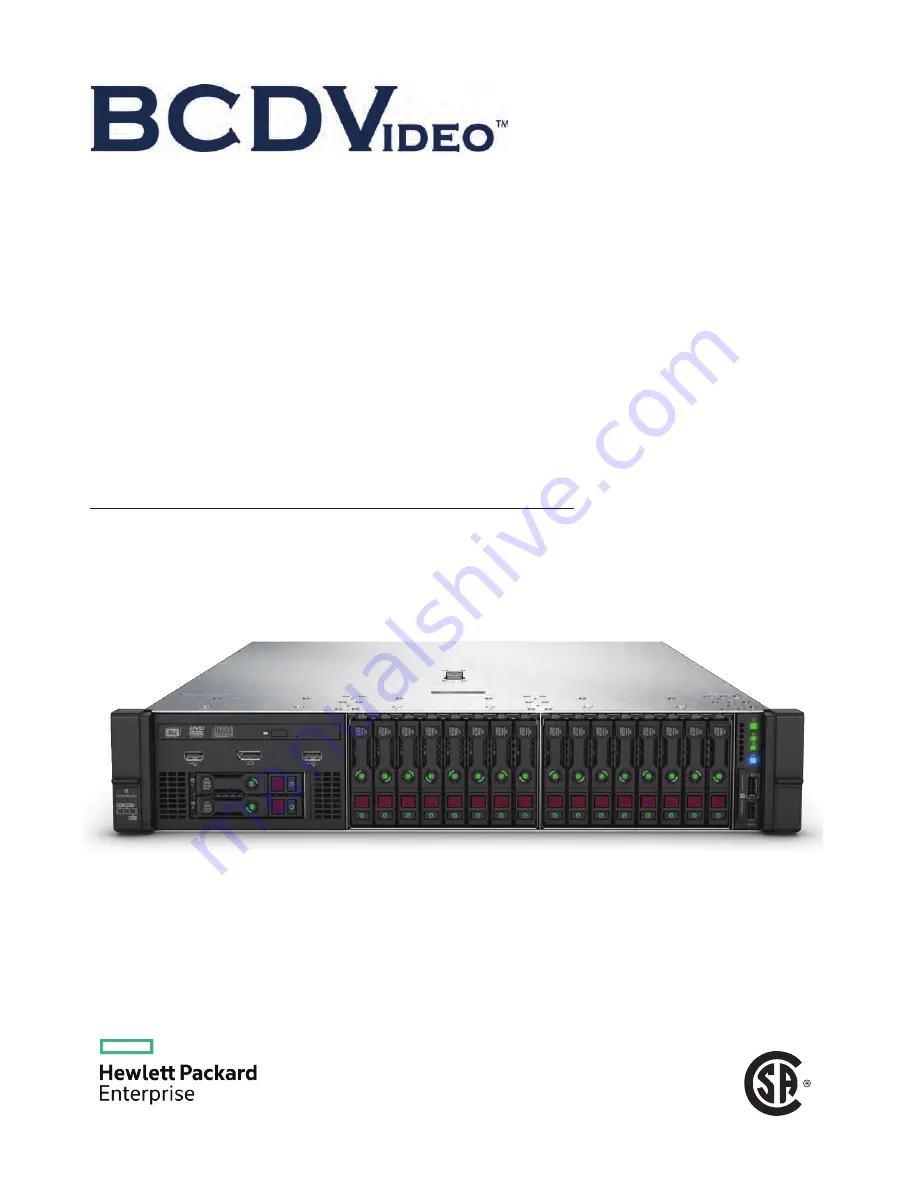
BCD221 SERVER
OEM
USER GUIDE
This document is for the person who installs, administers, and troubleshoots servers and storage systems. BCDVIDEO assumes you
are qualified in the servicing of computer equipment and trained in recognizing hazards in products with hazardous energy levels.
Summary of Contents for BCD221
Page 7: ...Documentation feedback 157 Contents 7 ...
Page 27: ...Component identification 27 ...
Page 43: ...Operations 43 ...
Page 124: ...Box 2 to SAS Expander All boxes 124 Cabling ...
Page 126: ...Box 2 Box 3 126 Cabling ...


