Bartec 17-51P6-1 11 Series, Operating Instructions Manual
The Bartec 17-51P6-1 11 Series is a cutting-edge device designed to meet all your technological needs. With its sleek and compact design, this product offers a wide range of features and functionalities. Ensure seamless operation with the accompanying operating instructions manual, available to download for free at manualshive.com.
Share
Download


Reviews:
No comments
Related manuals for 17-51P6-1 11 Series

PMF20
Brand: LOVATO ELECTRIC Pages: 4

Cooper Power Systems RLY-800
Brand: Eaton Pages: 14

1100A
Brand: CD Automation Pages: 84

Multilin 239
Brand: GE Digital Energy Pages: 160

XRS XR-980
Brand: Omnitracs Pages: 5

CSEZ-01/06
Brand: Moeller Pages: 4

Cutler-Hammer D64 Series
Brand: Eaton Pages: 19

AN Series
Brand: ALIND Pages: 54

ER-16
Brand: National Instruments Pages: 65
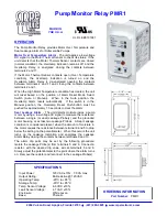
PMR1
Brand: MPE Pages: 2

LW821
Brand: Lightwave Pages: 16

EDS3HVAC
Brand: Esco Pages: 4

DIN Relay 4
Brand: Digital Loggers Pages: 15

CL-PK-MR2
Brand: Climax Pages: 2


