BART-TECH 3D BT1.2, Operating Manual
The "BART-TECH 3D BT1.2" operating manual is a comprehensive guide for users of this cutting-edge product. Get your free manual download from our website and unleash the full potential of your BT1.2. Unlock every feature, troubleshoot with ease, and maximize your device's capabilities with our user-friendly manual.
Share
Download


Reviews:
No comments
Related manuals for BT1.2

Elite 12N
Brand: GCC Technologies Pages: 63
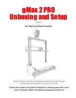
gMax 2 PRO
Brand: gCreate Pages: 9

Elite XL-1208
Brand: GCC Technologies Pages: 9

gMax 2 PRO
Brand: gCreate Pages: 21

Elite XL
Brand: GCC Technologies Pages: 199

DocuColor 6060
Brand: Xerox Pages: 4

PACEMARK 4410
Brand: Oki Pages: 215

2 Extended
Brand: Ultimaker Pages: 30

C931dn
Brand: Oki Pages: 320

Phaser 600
Brand: Tektronix Pages: 286

wematter Atmosphere
Brand: 3D Systems Pages: 11

PPT205
Brand: 3nStar Pages: 8

SKR E3 Turbo
Brand: BIG TREE TECH Pages: 11

Pronto 100
Brand: Magicard Pages: 42

Martrix Series
Brand: UnionTech Pages: 44

AGEP50 - COLOR VIDEO PRINTER
Brand: Panasonic Pages: 40

M1
Brand: Pandigital Pages: 2

TELEIOS HEXA
Brand: d.gen Pages: 65


