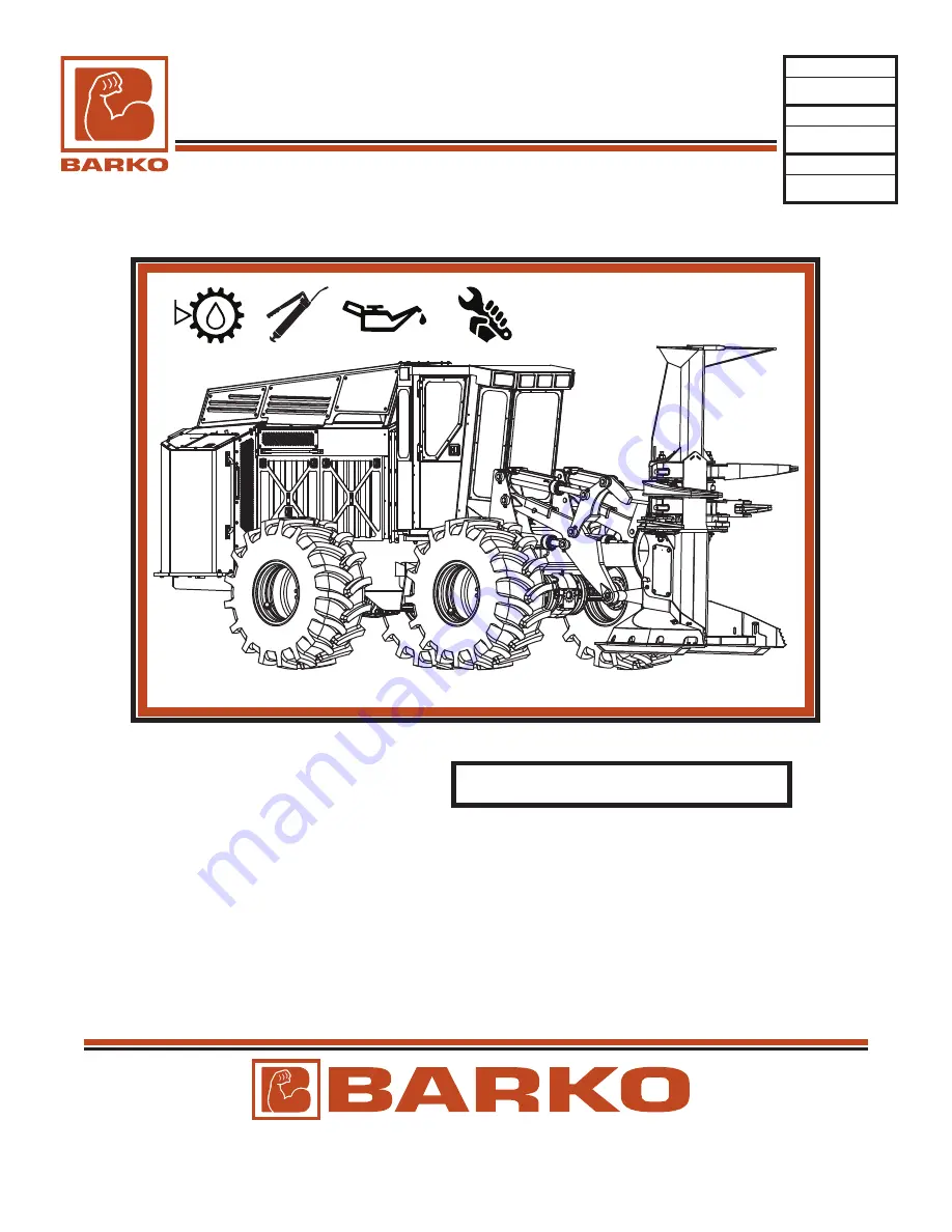
background image

®

SERVICE MANUAL

®

1 Banks Avenue • Superior • WI • 54880

Phone: 

800-544-6532 • 715-395-6700

Fax: 

800-772-2448 • 715-392-9348

Web: 

www.barko.com

   Email: 

[email protected]

MANUAL P/N

REVISION

DATE

Serial Number Range: 

Machine Serial Number: 

NOTE:

This Service Manual does not include safety, operation, or parts information.  Seperate Oprator’s and Parts Manuals are 

available for this machine and can be purchased through your Barko dealer. The Operator’s Manual include safety instructions 

which must be read and understood before operating or servicing this machine.  Keep the machine’s Operator’s Manual with 

the machine at all times.

The information and illustrations in this manual have been approved as accurate at the time of printing.  However, this manual 

may contain information on options not present on your loader. The right is reserved by Barko Hydraulics, LLC to make 

changes and improvements in its product at any time without notice or obligation.

Grapple and attachment information is not included in this manual. See separate Grapple and Attachment Owner’s, 

Installation, Parts and Service Manual(s) which accompanies all grapples from the factory.

800-00479

0

06/07/2019

WHEELED FELLER BUNCHER (WFB)

830B

11983025001 thru

Summary of Contents for 830B

Page 1: ...efore operating or servicing this machine Keep the machine s Operator s Manual with the machine at all times The information and illustrations in this manual have been approved as accurate at the time...

Page 2: ...ICING 13 4 PREVENTIVE MAINTENANCE 13 5 NEW MACHINE INSTRUCTIONS 13 5 INSPECTION SERVICE SCHEDULE 13 6 LUBRICATION FLUID SPECIFICATIONS 13 10 LUBRICATION FLUID POINTS WFB 13 14 TORQUE SPECIFICATIONS 13...

Page 3: ...SEL ENGINE 60 5 WFB 2PD PUMP DRIVE 535 07768 60 9 WFB TRAVEL PUMP 560 02701 60 17 WFB COOLING FAN PUMP 560 02941 60 25 WFB IMPLEMENT PUMP 560 02943 60 39 WFB SAW PUMP 560 02944 60 39 CH 65 DRIVETRAIN...

Page 4: ...THIS PAGE INTENTIONALLY BLANK SUPERIOR WI USA www barko com...

Page 5: ...INFORMATION 10 Table of Contents CHAPTER 10 USE GENUINE BARKO PARTS 10 2 WARNING HYDRAULIC PRESSURE 10 3 INTRODUCTION 10 4 KNOW YOUR BARKO 10 5 SAFETY SUMMARY 10 6 WELDING SAFETY 10 11 FIRE PREVENTIO...

Page 6: ...ist in performing service work A BARKO Operator s Manual will have safe operating procedures which may assist servicing your BARKO loader or attachment The Operator s Manual must be with the machine a...

Page 7: ...he machine and the operator from overloading When overloaded the machine can become stressed to a level where parts fracture causing death severe injury or property damage This is an extremely dangero...

Page 8: ...hand is determined when positioned in the machine from the normal operator s seat position behind the boom or lifting arms Cylinders The port location o center viewed from butt of cylinder Pump and M...

Page 9: ...n unsafe manner Never use a boom or attachment for a work platform or personnel carrier Serious injury or death may result When machine is not operating or when leaving cab boom or lift arm and attach...

Page 10: ...decals employer work rules and applicable government regulations Are trained and quali ed in safe machine operation and maintenance Consult supervisor to explain any unclear instructions and warnings...

Page 11: ...e to a zero energy state WARNING Mechanically connected controls will cause movement of components at all times EVEN IF PUMP OR ENGINE IS NOT OPERATING Always be certain that boom and attachment are p...

Page 12: ...applying hydraulic pressure WARNING If this machine is equipped with electric motor driven Auxiliary Oil Cooler be sure battery is disconnected before going near cooler fan If battery is not disconne...

Page 13: ...to work on machine with arms raised securely support machine and attachment WARNING Do not exceed 15 PSI nozzle pressure when drying parts with compressed air Do not direct compressed air against huma...

Page 14: ...dition of the machine Machine control and performance when operating on slopes may require special machine maintenance or more frequent intervals Fluid levels track tension or tire in ation pressure c...

Page 15: ...c Have a re extinguisher readily available Never ground an arc welder through turntable or boom bearings as arcing may occur causing bearing damage Always connect the welder ground cable to the compon...

Page 16: ...moving any twigs leaves straw rags uid spills or leaks dirt or grime Pay special attention to areas such as the engine engine cooling system exhaust system battery electrical connections brake systems...

Page 17: ...possible damage Check the safety pin to be intact Make sure the label instructions are clean and legible Check the needle indicator for designated pressure levels The green area is the charged zone D...

Page 18: ...ists Order Parts Access and download the latest pdf versions of Operators Parts and Service Manuals BARKO Dealer Net is the one stop online source to www barko com dnet Contact BARKO Machine Sales or...

Page 19: ...ww barko com BARKO DEALER NET continued SERVICE Access the latest Service Advisories and Bulletins Process and track Warranty Claims The screen shots showing BARKO Dealer Net may change over time 06 1...

Page 20: ...Linkage LUB Lubricate LWR Lower MAG Magnum MAG Magnum Plus MAINT Maintenance MAN Manual MATL Material MB Male SAE Boss MED Medium MH Material Handler MJ Male JIC ML Material Loader MLCH Mulcher MO Mal...

Page 21: ...E INSTRUCTIONS 13 5 INSPECTION SERVICE SCHEDULE 13 6 LUBRICATION FLUID SPECIFICATIONS 13 10 HYDRAULIC OIL 13 10 GREASE 13 10 GEAR OIL 13 10 DIESEL FUEL 13 11 ENGINE OIL 13 11 DEF DIESEL EXHAUST FLUID...

Page 22: ...Tank 10 gal 38 L Wheel Base 9 274 cm Engine Cummins QSL9 T4 w std 28L 26 20 ply Tire Package Weight w o ATT 33 250 lbs 15 080 kg Overall Height 10 8 1 2 326 cm Overall Length 20 8 630 cm Overall Widt...

Page 23: ...47 DRIVETRAIN chapter 65 POWER PACKAGE chapter 60 SHROUDING chapter 50 LIFTING ARMS chapter 30 ATTACHMENT chapter 35 OPERATOR S CAB chapter 40 COOLER AY chapter 60 FUEL RESERVOIR chapter 70 HYDRAULIC...

Page 24: ...chine If necessary to work on a lifted boom or attachment securely support the boom and attachment so that they cannot move or fall in any way Do not support the machine on cinder blocks hollow tiles...

Page 25: ...ved for type of welding Failure to obey warnings can cause death severe injury or property damage Instructions are necessary before doing service on loader See warnings and instructions both at the be...

Page 26: ...eci c maintenance procedures WARNING NOTICE remove flammable debris X check for wear and for loose or missing fasteners X inspect entire machine for stress wear cracks damage etc X grease all fittings...

Page 27: ...ck integrity X Emergency Escape s check X Air Filter s inspect and clean X replace if needed Air Filter s inspect and clean X replace if needed grease fittings X clean and inspect X clean and inspect...

Page 28: ...hange fluid X X change after initial 500 hours and every 1000 hours thereafter Engine perform 1000 hour or 1 year maintenance procedures X X see Section 6 in Cummins manual Engine perform 2 year maint...

Page 29: ...voirs Fitting check for leaks X Hydraulic Oil check level visually inspect oil quality X Hydraulic Tank Breather inspect X replace if defective Hydraulic Oil Filters Elements replace X X replace after...

Page 30: ...look for in an oil The hydraulic oil for the machine should feature Rust resistant additives to prevent rust formation from moisture condensation Anti foaming agents to break up air bubbles and preve...

Page 31: ...ea protected from dust moisture and other contaminants Store drums on sides The Cetane number should be 42 minimum For ambient temperatures above 0 C 32 F a minimum cetane number of 42 is required For...

Page 32: ...e diesel exhaust emissions from diesel engines The DEF you purchase should meet and display certification for one or more of the following standards American Petroleum Institute API German Institute o...

Page 33: ...olyethylene and polypropylene are recommended If DEF is spilled rinse and clean immediately with water Avoid prolonged contact with skin In case of contact wash with immediately with soap and water If...

Page 34: ...machine 3 LIFTING ARMS see next page chapter 30 7 AXLE ASSEMBLIES see service section in chapter 65 4 GREASE BULKHEAD see next page A B C D D E A Engine Oil chapter 60 D Pump Drive Ay chapter 60 B DE...

Page 35: ...eration and Service Manual for diesel engine service See separate manufacturer attachment manual s for attachment service 6 Transmission See Axle Section in Chapter 65 for service information 6 Axle A...

Page 36: ...ess functions of BARKO Hydraulics LLC unless otherwise noted NUT BOLT GRADES AND IDENTIFICATION UNIFIED THREAD STANDARD UTS ISO METRIC SCREW THREAD ACRONYMS DEFINITIONS UTS Uni ed Thread Standard UNC...

Page 37: ...66 1174 1950 2644 1170 1586 1 1 4 12 1240 1681 745 1010 2012 2728 1207 1636 2750 3728 1650 2237 1 3 8 12 1670 2264 1000 1356 2712 3677 1627 2206 3700 5017 2220 3010 1 1 2 12 2200 2983 1320 1790 3557 4...

Page 38: ...3 72 47 64 12 1 75 55 75 49 66 79 107 70 95 92 125 81 110 14 2 00 88 119 78 106 126 171 111 150 147 199 130 176 16 2 00 137 186 121 164 196 266 173 235 229 310 202 274 18 2 50 189 256 167 226 270 366...

Page 39: ...75 95 129 63 85 14 2 00 155 210 105 142 16 2 00 235 319 160 217 18 2 00 20 2 50 460 624 305 414 22 2 50 625 847 415 563 24 3 00 790 1071 525 712 Dia mm Pitch Class 12 9 Dry Lubricated NOTICE Threads...

Page 40: ...BARKO WFB for over the road transportation Do not put chains over or against electrical wires or hydraulic lines or hoses Carefully drive the machine up on the trailer Make certain the trailers in on...

Page 41: ...ers to keep a thin lm of oil on the cylinder shafts and seals Keep all cylinders in RETRACTED POSITION TURN OFF the Main Electrical Disconnect MED Switch With the MED switch in the o position some mod...

Page 42: ...THIS PAGE LEFT INTENTIONALLY BLANK...

Page 43: ...20 7 HYDRAULIC VALVES MANIFOLDS 20 9 HYD VALVES 20 10 FRONT VALVE 558 02174 20 10 STEERING VALVE 558 02175 20 11 HYD MANIFOLDS 20 13 PILOT DRIVE MANF 563 01196 20 13 BOOST FLUSHING MANF 563 01203 20...

Page 44: ...20 2 SUPERIOR WI USA www barko com Part No 605 01591 HYD AY WFB 830B 05 30 2019 Updated SERVICE...

Page 45: ...20 3 SUPERIOR WI USA www barko com Part No 605 01591 HYD AY WFB 830B 05 30 2019 Updated SERVICE...

Page 46: ...20 4 SUPERIOR WI USA www barko com Part No 607 00229 SCHEM HYD IWT FB 280 280 200 n max min T1 P1 PX PS YS PL LS 300 T2 B A B 330 YXX EK2 05 30 2019 Updated SERVICE...

Page 47: ...USA www barko com Part No 607 00229 SCHEM HYD IWT FB n T1 P1 PX PS YS PL LS 300 T2 LSP A B A B 330 330 YXX EK2 A B A B 330 330 TRX EK2 A B 315 315 330 330 RAX K1 A B 315 315 330 330 RAX EK2 05 30 2019...

Page 48: ...THIS PAGE LEFT INTENTIONALLY BLANK...

Page 49: ...2950 LS PORT IDLE ACC ARMS OPEN RETRACT 4000 3950 4050 LS PORT IDLE GRAB ARMS OPEN RETRACT 4000 3950 4050 LS PORT IDLE ATTACHMENT PUMP STANDBY 435 420 450 ATT PUMP FWD PRESSURE OVERRIDE 4000 3950 4050...

Page 50: ...THIS PAGE LEFT INTENTIONALLY BLANK...

Page 51: ...r references for more information on these components All valve and manifold locations are NOT shown in these illustrations Refer to BARKO Parts Manuals for locations and parts illustrations for all c...

Page 52: ...1 Fig 2 1 FRONT VALVE ASSEMBLY Fig 1 1 1 Solenoid Valves Fig 2 5 1 3 4 2 Bleeding Solenoid Valves Check escaping oil for air content If air bubbles repeat point 3 Start system and leave idling Unscrew...

Page 53: ...20 11 HYD VALVE WFB STEERING 558 02175 Fig 1 1 STEERING VALVE ASSEMBLY Fig 1 STEERING CYLS R L L CYL BUTT R CYL ROD L CYL ROD R CYL BUTT INLET MANIFOLD END SECTION 05 30 2019 Updated SERVICE...

Page 54: ...THIS PAGE LEFT INTENTIONALLY BLANK...

Page 55: ...sure Reducing Valve Ensures there is su cient pressure to stop the machine on demand 3000 PSI is the factory recommended pressure value Pilot Pressure Reducing Valve Ensures there is enough pilot pres...

Page 56: ...ar Pump brake pedal until circuit is charging or use Brake Needle Valve NV to release pressure Verify brake pressure max Note If 2800 PSI 193 1 bar has been achieved move onto step 13 if not repeat st...

Page 57: ...achine Install pressure transducer or 5000 PSI gauge on PRGP port Turn on Control Power Loosen jam nut on the Pilot Pressure Reducing Valve Pr2 1 3 Pilot Di erential Pressure Setting Procedure 9 8 10...

Page 58: ...auge on G2 port on the Boost Flushing Manifold Fig 1 Start machine Turn on attachment Lift attachment o ground Note Attachment will be rotating while adjusting relief Set the Flushing Relief Valve pre...

Page 59: ...2 Install pressure transducer or 1000 PSI gauge on G Port on the Attachment Pump Manifold Fig 3 Loosen the Jam Nut on the Return Manifold Relief Valve Fig 1 Tighten jam nut on the Return Manifold Reli...

Page 60: ...THIS PAGE LEFT INTENTIONALLY BLANK...

Page 61: ...d parts illustrations for all components refer to Chapter 60 in BARKO Manuals for more information 1 1 WFB POWER PACKAGE Pumps Manifolds Fig 1 Fig 1 PUMP DRIVE 2 Pad transfers rotation from engine to...

Page 62: ...psi pressure gauge in the pump charge pressure gauge port M3 Install a 10 bar 100 psi gauge to measure case pressure tee into L1 or L2 or use servo gauge port M4 or M5 Operate the system with the pump...

Page 63: ...the LS Adjustment Note Verify the Standby Pressure does not change after you have tightened the set screw Start machine Turn on control power Loosen set screw on the LS Adjustment Install pressure tra...

Page 64: ...reached and maintained 425 PSI is the factory recommended standby pressure value 4500 PSI is the factory maximum system pressure value 1 Saw Pump Maximum Displacement Adjusting Procedure refer to Fig...

Page 65: ...ressure transducer or 5000 PSI gauge on M2 Port of the saw pump Turn on control power Run engine at quarter throttle 1175 RPM Loosen set screw on the LS Adjustment Fig 2 8 12 9 10 11 13 15 14 Return e...

Page 66: ...uses of air being introduced into a hydraulic system are loose connections and ttings This not only creates aeration in the uid but also provides the risk of contamination entering the uid and compone...

Page 67: ...SAE Code 61 4 bolt split ange There are two types of ange port connections One captive or two split ange clamps A body ange head Four bolts and washer Fig 1 1 FLANGE PORT ASSEMBLY 6 4 5 2 3 1 Positio...

Page 68: ...eals note position they are in for proper reassembly see diagram on next page 7 Clean and inspect all parts If worn or damaged replace them CYLINDER SERVICING RE SEAILING Cylinder shown may not be typ...

Page 69: ...and piston is in proper orientation small recess is O ring side large recess is nut side 11 Tighten nut to torque listed in parts manual 12 Oil new cylinder seals lightly before installing rod assemb...

Page 70: ...THIS PAGE LEFT INTENTIONALLY BLANK...

Page 71: ...3 22 15 HARNESS AY DOS INJ DLM SUPPLY 954 01534 22 15 HARNESS AY BOC RT REAR FRAME 954 01563 22 16 HARNESS AY BOC LT REAR FRAME 954 01564 22 17 HARNESS AY BOC RT REAR FRAME 954 01563 22 18 HARNESS AY...

Page 72: ...the two basic circuits there is an accessories circuit and operating light circuit s Charging circuit alternator and battery Disconnect battery ground cable before making any repairs to electrical cir...

Page 73: ...ates and sheet references to navigate from one system or connection to another The D8 tells the user the Map Coordinates on that sheet where this connection connects to SHEET NUMBER MAP COORDINATES Us...

Page 74: ...0 W15 6 973 00860 W16 2 973 00860 W16 6 973 00860 W1 R2 973 00860 W17 6 973 00860 W20 4 973 00860 W23 L2 973 00860 W24 R1 973 00860 W24 L2 973 00860 W25 L2 973 00860 W27 R2 973 00860 W32 R2 973 00860...

Page 75: ...00860 P3 78 973 00860 P3 12 973 00860 F10 1 973 00860 P3 77 973 00860 P3 85 973 00860 W59 L1 973 00860 W59 L2 973 00860 P3 29 973 00860 P3 5 973 00860 P3 4 973 00860 J27 5 973 00860 P3 56 973 00860 F1...

Page 76: ...J8 1 2 3 4 548 02932 973 00860 C1 66 973 00860 SP6 1 973 00860 P8 A 973 00860 J5 1 973 00860 SP2 1 973 00860 T8 1 973 00860 K9 T15 1 973 00860 J27 10 973 00860 P3 16 973 00860 P3 97 973 00860 P3 2 97...

Page 77: ...ST2 T26 1 973 00860 P3 59 973 00860 W45 R1 973 00860 P3 58 973 00860 W48 R1 973 00860 P3 10 973 00860 W44 R1 973 00860 P3 61 973 00860 W47 R1 973 00860 P3 27 973 00860 W50 R1 973 00860 W43 R1 973 008...

Page 78: ...40 P10 4 P7 1 2 3 4 548 02931 954 01541 SP1 1 954 01541 954 01541 SP1 1 954 01541 SP2 1 954 01541 SP2 1 P8 1 2 3 4 5 6 548 02379 954 01541 R 1 954 01541 R 1 954 01541 L 1 954 01541 L 1 954 01541 T1 1...

Page 79: ...A6 5 A6 5 A6 J1 1 REAR LIGHT 2 548 02908 J2 1 REAR LIGHT 2 548 02908 J3 1 REAR LIGHT 2 548 02908 J4 1 REAR LIGHT 2 548 02908 L 548 03941 L LEFT SPEAKER R 548 03941 R RIGHT SPEAKER T1 DOME LIGHT T2 548...

Page 80: ...954 01542 J10 34 954 01542 J10 35 954 01542 J6 86 954 01542 J6 87 P4 1 HVAC PEDESTAL 2 3 4 548 02982 P16 1 EGRESS DOOR LOCK SWITCH 2 3 4 548 02982 TO BOC 1 TO BOC 3 TO BOC 2 TO BOC 4 954 01542 18AWG...

Page 81: ...42 J6 1 954 01542 J6 43 954 01542 J6 60 954 01542 J6 29 954 01542 J6 30 954 01542 J6 31 954 01542 J6 32 954 01542 J6 33 954 01542 J6 34 954 01542 J6 35 954 01542 J6 36 954 01542 J6 37 954 01542 J6 95...

Page 82: ...8 02275 J19 1 PNEUMATIC SYS PRESS SW 2 548 02908 J3 1 BACK UP ALARM PRESS SW 2 548 02908 J4 1 BRK PRESS SW 2 548 02908 P4 1 WINCH SWITCH NOT USED 2 4 548 02982 3 954 01564 P1 1 954 01564 P1 3 954 0156...

Page 83: ...01564 P1 18 954 01564 P1 19 954 01564 P1 20 954 01564 P1 21 954 01564 P1 22 954 01564 P1 23 954 01564 P1 24 954 01564 P1 25 954 01564 P1 26 954 01564 P1 27 954 01564 P1 28 954 01564 P1 29 954 01564 P...

Page 84: ...NT LVL B C 548 04103 J29 1 DEF TANK HEAT VLV 2 3 4 548 04495 J30 A B C 548 02617 J32 A B C 548 02617 J24 1 DEF LINE HTR 1 2 548 02908 J25 1 DEF LINE HTR 2 2 548 02908 J26 1 DEF LINE HTR 3 2 548 02908...

Page 85: ...8 03387 J1 1 2 3 4 5 6 7 8 9 10 11 12 548 04295 J3 1 2 548 02908 P1 1 2 3 4 5 6 7 8 548 03423 954 01564 J32 A 954 01564 J32 B 954 01564 J18 10 954 01564 J18 11 954 01564 SP12 1 954 01564 SP10 1 120OHM...

Page 86: ...2617 954 01563 P2 1 954 01563 P2 2 954 01563 P2 3 954 01563 P2 4 954 01563 P2 5 954 01563 P2 6 954 01563 P2 7 954 01563 P2 8 954 01563 P2 9 954 01563 P2 10 954 01563 P2 11 954 01563 P2 12 954 01563 P2...

Page 87: ...SP3 1 954 01564 SP13 1 954 01564 J27 1 954 01564 J27 2 954 01564 SP14 1 954 01564 J28 B 954 01564 SP15 1 954 01564 J29 1 954 01564 J24 1 954 01564 J25 1 954 01564 J26 1 954 01564 J30 A 954 01564 J30 B...

Page 88: ...4 01563 SP9 1 954 01563 J6 83 954 01563 P2 17 954 01563 J9 E6 954 01563 J9 E2 954 01563 SP4 1 954 01563 J9 D1 954 01563 SP7 1 954 01563 SP1 1 954 01563 SP7 1 954 01563 SP2 1 954 01563 SP7 1 954 01563...

Page 89: ...DEF TANK HEAT VLV AWG18 BLU TXL ECM RET SW TEMP LVL AWG16 BLK TXL ENG COOLANT LEVEL AWG18 YEL TXL WATER IN FUEL AWG18 GRN TXL ANLG ACCEL POS 2 SPLY AWG16 RED TXL OEM RETURN AWG16 BLK TXL GRID HTR RLY...

Page 90: ...48 02908 J3 1 FLOAT ON OFF NOT USED 2 548 02908 P1 1 2 3 4 548 02982 954 01565 P9 1 954 01565 P9 2 954 01565 P9 3 954 01565 P9 4 954 01565 P9 5 954 01565 P9 6 954 01565 P9 7 954 01565 P9 8 954 01565 P...

Page 91: ...136 T27 548 01136 REMOTE TERM T28 548 01136 T29 548 01136 ENGINE BLOCK T30 548 04604 T31 548 04604 FRAME T14 548 03267 T13 548 01111 T1 548 03275 T3 548 01031 T4 548 01031 T1 548 01636 T2 548 01111 T3...

Page 92: ...LICS L L C DATE ECO DESCRIPTION OF CHANGE DATE REV BY APPROVED BY DECIMAL 0 00 0 06 0 000 0 030 0 0000 0 0050 ANGULAR 0 5 NTS SCHEM EL 830B 903 00332 0 19 20 CJL LJS 7 20 18 10 19 18 LJS CJL 18009 INI...

Page 93: ...WT ALL RIGHTS TO MANUFACTURE COPY REPRODUCE OR DISPOSE OF THIS DRAWING OR ITS CONTENTS ARE RESERVED UNLESS OTHERWISE SPECIFIED IN WRITING BY BARKO HYDRAULICS BARKO HYDRAULICS L L C DATE ECO DESCRIPTI...

Page 94: ...THIS PAGE LEFT INTENTIONALLY BLANK...

Page 95: ...B HARN CONN 955 00249 0 1 7 CJL LJS 7 23 18 10 19 18 LJS CJL 18009 INITIAL RELEASE 7 23 18 P1 548 05272 TO 973 00860 J27 J8 548 02382 TO 954 01541 J7 548 02932 TO 954 01541 P3 548 02982 CAB DOOR SWITC...

Page 96: ...4 8 0 5 2 7 1 ALARM BUZZER T6 548 05271 ALARM BUZZER 0 1 2 ADD0 548 05269 1 1 2 ADD1 548 03165 ORG BLU BLU P4 548 02781 ORG BLU BLU P5 548 02781 ORG BLU BLU P6 548 02781 ORG BLU BLU P7 548 02781 ORG...

Page 97: ...O WT ALL RIGHTS TO MANUFACTURE COPY REPRODUCE OR DISPOSE OF THIS DRAWING OR ITS CONTENTS ARE RESERVED UNLESS OTHERWISE SPECIFIED IN WRITING BY BARKO HYDRAULICS BARKO HYDRAULICS L L C DATE ECO DESCRIPT...

Page 98: ...04482 DEF SUPPLY MODULE 548 02981 J22 DEF TANK T5 548 01031 BACK UP ALARM T6 548 01031 BACK UP ALARM T7 548 01031 FUEL LVL T8 548 01031 FUEL LVL J2 548 05157 FAN DOOR PROX SW J28 548 04103 COOLANT LEV...

Page 99: ...NN T2 548 01780 A C COMP CLUTCH 548 02981 J3 HYD TEMP F1 548 03532 5A 548 03557 IGN INPUT FUSE 548 05145 P3 TO J3 OF 954 01530 T3 548 01031 GRID HTR COIL T4 548 01031 GRID HTR COIL J1 548 03581 BOC CO...

Page 100: ...00249 0 6 7 CJL LJS 7 23 18 10 19 18 LJS CJL 18009 INITIAL RELEASE 7 23 18 1 3 2 4 1 3 2 4 1 3 2 4 1 3 2 4 P1 P2 P3 P4 P5 548 03423 P1 J23 OF 954 01529 548 02617 J2 P2 OF DLM J3 548 04487 SCR TEMP J4...

Page 101: ...RTER LUG T10 548 04607 3 POS FUSE SUPPLY T11 548 04607 ALT FUSE 200A T12 548 04926 ALTERNATOR T13 548 04794 GRID HTR FUSE 250A T14 548 04794 GRID HTR SOL T15 548 04927 GRID HTR SOL T16 548 04797 GRID...

Page 102: ...THIS PAGE LEFT INTENTIONALLY BLANK...

Page 103: ...IITIONING A C SYSTEM 26 3 HVAC SERVICE SCHEDULE 26 4 HVAC SERVICING 26 5 A C CHARGING PROCEDURE 26 6 ALTERNATE A C CHARGING PROCEDURE 26 7 A C PRESSURE TEMP CHART 26 7 DIAGNOSING EXPANSION VALVE SYSTE...

Page 104: ...THIS PAGE LEFT INTENTIONALLY BLANK...

Page 105: ...rigerant ow The location of each component is in parenthesis Allow only certi ed personnel to service and maintain the air conditioning system The Clean Air Act of 1992 states that anyone who works on...

Page 106: ...s 2 amps 24 volts Tubes inspect for obvious dents oil stains dirt indicating leakage X Condenser Fins clean away dirt and bugs staighten if necessary X Moisture Indicator check either remote mounted o...

Page 107: ...at low RPM serious injury may occur Never use compressed air to leak test or pressure test an R134a system Under certain conditions pressurized mixtures of R134a and air can be combustible In additio...

Page 108: ...arging scale measurement 15 Open red high side valve on manifold gauge set and add the factory recommended charge amount Close red valve on manifold gage set Charging is complete Verify proper a c ope...

Page 109: ...coil and not the coil surfaces Add to temperature for coil air o temperatures 8 10f CONDENSER temperatures are not ambient temperatures Add to ambient 35 40 F for proper heat transfer then refer to pr...

Page 110: ...riction or replace necessary components Evacuate and recharge the system Normal to Low Normal Unit works ne for a while Evaporator freeze up Replace thermostatic switch 0 25 PSI 150 285 PSI then begin...

Page 111: ...compressor and other A C system components 1 1 Fig 1 General Layout of HVAC on 830 WFB Fig 1 The following pages in this sub section are machine speci c for 830 WFB HVAC Systems CAUTION Condenser Com...

Page 112: ...16937 and after 1 2 548 04558 A C HEATER UNIT 1 2 1 Fig 2 548 04558 Parts Illustration see parts manual for part numbers and descriptions Fig 2 1 2 3 4 5 6 7 8 1 Expansion Coil 2 Heater Core 3 Expansi...

Page 113: ...26 11 SERVICE HEATER AC UNIT WFB continued 1 2 2 Fig 3 548 04558 Schematic Fig 3 05 31 2019 Updated SERVICE...

Page 114: ...THIS PAGE LEFT INTENTIONALLY BLANK...

Page 115: ...RIOR WI USA www barko com P 800 544 6532 F 800 772 2448 Support barko com SERVICE ATTACHMENTS 35 Table of Contents CHAPTER 35 WFB ATTACHMENTS 35 2 REPLACEMENT PARTS 35 2 SERVICE REPAIRS 35 2 HYDRAULIC...

Page 116: ...ted below should NEVER be exceeded for the attachment hydraulic circuit even if the attachment can accept higher pressures and or ows See Chapter 20 in your BARKO Service Manual for machine pump and p...

Page 117: ...the illustration below Incorrect hydraulic hose hook ups may cause damage to machine and or attachment as well as injury to operator or bystanders Fig 1 VIEWING FROM FRONT OF MACHING ACCUMULATE CYL B...

Page 118: ...THIS PAGE LEFT INTENTIONALLY BLANK...

Page 119: ...AR FRAME OVERVIEW 47 2 SPECIAL TORQUES 47 3 FRONT VALVE AY K220LS 558 02174 47 4 STEERING VALVE AY L90LS 558 02175 47 5 HYD CONTROL VALVE OVERVIEW 47 7 K220LS HYD VALVE 47 7 INLET SECTION 47 8 END SEC...

Page 120: ...vice parts information for components in this assembly Contact your BARKO dealer to acquire these manuals 1 WFB FRONT REAR FRAME OVERVIEW See Fig 1 for the major components of the WFB frame See the fo...

Page 121: ...te 242 1 Torque to 100 ft lbs use Blue Loctite 242 1 1 3 Fig 1 2 Loose or over torqued bolts can cause death severe injury or property damage Maintain proper bolt torque Visually check bolts daily Che...

Page 122: ...bile Directional Control Valve 1 VALVE SECTION DESCRIPTIONS Fig 1 NOTICE For general service information for this valve see the K220LS Valve section later in this chapter For service parts information...

Page 123: ...VALVE 1 VALVE SECTION DESCRIPTIONS Fig 1 1 RETURN 2 STEERING 3 INLET NOTICE For general service information for this valve see the L90LS Valve section later in this chapter For service parts informati...

Page 124: ...THIS PAGE LEFT INTENTIONALLY BLANK...

Page 125: ...48 8 SEC 240B 260B 558 02174 FRONT 830B not all BARKO K220LS valve con gurations listed above The K220LS is a sectionally built load sensing directional control valve for mobile machinery The valve is...

Page 126: ...ineral base oil of high quality and cleanness in the hydraulic system Hydraulic uids of type HLP DIN 51524 oil for automatic gearboxes Type A and engine oil type API CD can be used Hydraulic Fluids Vi...

Page 127: ...kdowns for your K220LS Control Valve Figures 1 4 are general K220LS valve cutaways to show common con gurations and major components Fig 4 Spool Actuator Spool Actuator Spool Pressure Relief Valve A W...

Page 128: ...ality and doesn t operate proportionally as usual This means for example that the solenoid may operate much faster than usual and the unexpected speed could cause crushing or other injuries 2 1 Manual...

Page 129: ...directional valve for mobile machines It is designed for working pressures of up to 320 bar and a maximum pump ow of 200 l min The valve can be given excellent simultaneous operating characteristics...

Page 130: ...nloading function BEN 22 Counter pressure valve MF 33 Separate tank connection for pilot circuit TP 40 Pilot pressure connection PS Pilot coarse lter S 39 Internal pilot pressure supply R 37 Pump conn...

Page 131: ...Port relief valve PA service port A 76 Port relief valve PA service port B 76 Spool actuator C 50 NOTICE 1 1 3 Spool Actuators Fig 4 breakdowns for your L90LS Control Valve Figures 1 4 are general L90...

Page 132: ...the unexpected speed could cause crushing or other injuries An Override Tool must be used to engage the manual override function of the solenoid Use of other tools to attempt to engage or disengage th...

Page 133: ...THIS PAGE LEFT INTENTIONALLY BLANK...

Page 134: ...THIS PAGE LEFT INTENTIONALLY BLANK...

Page 135: ...DISASSEMBLY 60 11 REASSEMBLY 60 13 LUBRICATION 60 15 OIL SPECIFICATIONS CAPACITIES 60 15 PUMP CUT AWAY ILLUSTRATION 60 16 WFB TRAVEL PUMP 560 02701 60 17 SERIES 90 HYDRAULIC PUMP DESCRIPTION 60 18 PUM...

Page 136: ...AW PUMP 560 02944 60 39 SERIES 45 HYDRAULIC PUMP DESCRIPTION 60 40 PUMP SETTINGS see chapter 20 60 40 REPLACEMENT PARTS 60 41 MINOR REPAIR 60 41 SHAFT SEAL REPLACEMENT 60 41 AUXILIARY PADS 60 42 LS PC...

Page 137: ...r Package See your Cummins manual for more detailed components of the diesel engine NOTICE Fig 1 IMPLEMENT PUMP SAW PUMP TRAVEL PUMP FAN PUMP DEF TANK DEF SUPPLY MODULE AIR INTAKE AFTERTREATMENT ENGIN...

Page 138: ...THIS PAGE LEFT INTENTIONALLY BLANK...

Page 139: ...ck Engine Steam Cleaning Clean Aftertreatment Diesel Exhaust Fluid Dosing Unit Filter Change Overhead Set Adjust Maintenance Procedures at 5000 Hours or 4 Years Maintenance Procedures at 4500 Hours or...

Page 140: ...he Engine Oil Dip Stick Fig 1 Ensure the oil level is between MIN and MAX lines on the dip stick Add oil if low Open the RH Engine Compartment Access Door to gain access the engine compartment 3 1 2 C...

Page 141: ...s the engine compartment Follow steps in Section 5 of your Cummins manual for changing the Fuel Filter 3 3 Checking and Changing Engine Coolant Do not open the ller cap when the engine is warm Steam o...

Page 142: ...e the indicator readout Fig 9 Located on the Air Filter Housing Check the intake tubes and clamps between the air cleaner and the turbocharger Replace any tubes that are cracked or damaged Tighten loo...

Page 143: ...ounts directly to the engine ywheel Use extreme care when mounting the drive plate to the engine ywheel to avoid pre loading the crankshaft bearings 1 2 3 Bolt the drive plate to the engine ywheel see...

Page 144: ...des a separate installation parts and service manual 1 3 Clutch Driven 3 1 2 4 Lubricate the included o ring with oil and install it onto the hydraulic pump pilot Do not use the engine adapter mountin...

Page 145: ...s that the pumps be removed 4 If replacing the pump pads remove the cap screws or nuts Use a large screwdriver to evenly pry the pump pads loose of the gear box Be careful to lift the pump pads evenly...

Page 146: ...val To remove the gears and bearings swiftly and evenly lift from the housing This can be done by hand as the bearings are a slip t see Fig 3 When rotating gears keep hands and ngers clear from the ge...

Page 147: ...any contaminates or visual defects With a clean towel or rag wipe the housings clean The gears have retaining ring grooves on the output side and a seal lip on the input side Install the gears into t...

Page 148: ...per torque speci cations Turn over the assembled gear box to install the input seal Apply a small coat of oil to the gear surface to allow the seal to properly seat Apply a thin coat of Loctite 609 to...

Page 149: ...apters and the input shaft are exposed to the oil within the pump drive do not apply grease or any type of corrosion prevention materials to the splines as these will contaminate the gear box oil 4 LU...

Page 150: ...7 D 2 38 Qts 2 25 L 2 80 Qts 2 65 L 1 18 I 3 50 Qts 3 31 L 2 30 Qts 2 18 L 1 48 D 3 25 Qts 3 07 L 2 50 Qts 2 36 L 1 40 D 3 13 Qts 2 96 L 1 1 3 62 Qts 3 43 L 3 00 Qts 2 84 L 1 25 D 1 18 D 2 75 Qts 2 60...

Page 151: ...rvicing a hydraulic system Unintended Machine Movement while servicing Unintended movement of the machine or mechanism may cause injury to the technician or bystanders To protect against unintended mo...

Page 152: ...on of uid ow The Basic Closed Circuit direction from the pump to the motor then back to the pump in this closed circuit Either of the hydraulic 1 3 Cross Section Illustration Fig 1 Hydraulic lines con...

Page 153: ...Flush the lines before replacing the hydraulic uid Before replacing the pump on the machine replace all lters and drain and ll the hydraulic system with the correct hydraulic uid 3 2 Shaft Seal and S...

Page 154: ...e shaft and bearing for rust wear or contamination Spin the bearing in your hand feeling for roughness Replace if necessary 3 2 2 Reassembly 6 2 1 4 3 5 Using the arbor press press the new seal L40 in...

Page 155: ...in su cient control to prevent the internal components from ying loose Do not damage parts during disassembly Remove internal parts P07 P08 P17 P16 P15 P14 P09 and P11 Remove and discard O ring P02 Mu...

Page 156: ...11 and P12 Place the cartridge in a vise and press on the poppet seat P12 Lubricate and install new O rings P02 P06 P13 Install bypass actuator P03 with pressure limiter valve P01 Torque to 40 N m 30...

Page 157: ...a large screwdriver or 1 2 inch hex wrench Remove and discard the O ring K50 Remove the screw adjustable charge relief valve plug by loosening the lock nut 3 2 3 4 2 Inspection Inspect the poppet K80...

Page 158: ...e lter head and lock nut sealing surfaces If you nd any nicks or scratches replace the damaged components 3 4 1 Reassembly Install the hydraulic tube N25 into it s bore in the endcap Install the lter...

Page 159: ...pumps are shown above 560 02940 T6 20 14 937B 560 02941 T6 22 830B 560 02933 T6 22 14 937B 560 02930 T6 20 14 937B 560 02931 T6 22 14 930B WARRANTY Before beginning repairs on manufacturer components...

Page 160: ...ays in the rear cap Fig 3 General Cartridge Assembly see Fig 3 2 PUMP SERVICE REPAIR 2 1 Pump Disassembly Double Vane Pump steps shown see Fig 2 for reference 1 2 3 After pump is removed from machine...

Page 161: ...ouble Vane Pump steps shown see Fig 2 for reference 4 Disassemble the P2 cartridge end cap with a wheel bearing puller Fig 5 Fig 7 Fig 5 Fig 6 5 Put two screws in the housing and ip the pump housing P...

Page 162: ...8 Fig 10 Fig 8 Fig 9 8 Disassemble the P1 cartridge front cap with a wheel bearing puller Fig 9 Take a protection cone to prevent seal damage If you don t change the shaft seal see Fig 10 for A B A R...

Page 163: ...ntinued Housing Retaining ring End cap Shaft assembly Cartridge P2 Key Cartridge P1 Front cap Shaft seal 2 1 Pump Disassembly Double Vane Pump steps shown see Fig 2 for reference 9 Shaft seal out Fig...

Page 164: ...P1 into the housing A Protective cone on the shaft assembly If the shaft is bigger than the shaft seal please contact BARKO Service B Shaft assembly protective cone into the front cap Slightly rotate...

Page 165: ...the front cap and shaft is blocked at 1 2 parcours rotate the shaft manually Always check if the shaft rotates a slight torque due to the spring loaded resistance force Otherwise please go back to the...

Page 166: ...housing dowel pin hole Put some grease on the seals to prevent them from moving Always check if the shaft rotates freely If not disassemble and go back to the previous step Check if the dowel pin is i...

Page 167: ...eck if the shaft rotates If not disassemble and go back to the previous step Pump Component Torque Always check if the shaft rotates a slight torque due to the spring loaded resistance force Otherwise...

Page 168: ...ine as examples d 5 Check if the pump is not located too high above the oil level d 6 Check if the tank is not completely sealed Then the lack of atmospheric pressure will not allow the pump to prime...

Page 169: ...fore sticking some vanes in the rotor or blocking the vein uid b 3 Check if the pump is not too high compared to the oil level or if the pump is not too far from the tank check the inlet absolute pres...

Page 170: ...vailable ow and therefore cannot build up pressure a 1 Check the hydraulic circuit schematic a 8 Check if the inlet pipe is under the oil level b 2 Check the pressure piping and see if its length dump...

Page 171: ...s working correctly or well dimensioned b 3 Check if the inlet pressure is not over or under the catalog values This has to be done for the whole cycle because the inlet pressure can vary from time to...

Page 172: ...THIS PAGE LEFT INTENTIONALLY BLANK...

Page 173: ...hydraulic system while servicing Unintended Machine Movement Unintended movement of the machine or mechanism may cause injury to the technician or bystanders To protect against unintended movement se...

Page 174: ...m the reservoir through the inlet line The pump outlet feeds a PVG 32 multi section load sensing directional control valve The PVG valve directs pump ow to the cylinder and gear motor Flow in the circ...

Page 175: ...e the seal 3 1 2 Installation 1 2 3 wear or contamination Polish the sealing area on the shaft if necessary Inspect the pump housing and new seal for damage Inspect the sealing area on the shaft for r...

Page 176: ...hown Remove the shipping cover or auxiliary pump and its seal J120 Remove the drive coupling J140 if present 3 2 2 Installation 3 1 2 4 Install the drive coupling J140 if present Lubricate new O rings...

Page 177: ...C105A or the plug C106 and O ring C106A Discard the O ring C105A or C106A Remove the LS set screw C102 LS adjusting plug C118 O ring C118A back up rings C118B springs C114 C115 and seat C113 Discard...

Page 178: ...all and torque the LS set screw C102 to 9 N m 7 lbf ft Install the control assembly onto the endcap using the 4 screws C300 Torque the screws to 6 N m 5 lbf ft Torque screws in a criss cross pattern a...

Page 179: ...stall the servo control ori ce G020 and torque to 2 7 N m 24 in lb Then install the ori ce backup plug G030 and torque to 2 7 N m 24 in lb Install the PC spool C132 spherical end rst into the PC bore...

Page 180: ...ng the four screws C300 Torque the screws to 6 4 N m 4 7 lbf ft Torque screws in a criss cross pattern and re torque the rst screw to ensure proper torque retention Check and adjust the control settin...

Page 181: ...THIS PAGE LEFT INTENTIONALLY BLANK...

Page 182: ...THIS PAGE LEFT INTENTIONALLY BLANK...

Page 183: ...60 GEARBOX TRANSMISSION 65 9 MAINTENANCE 65 9 GEAR OIL DRAIN FILL 65 9 SERVICE SCHEDULE 65 10 EXPLODED VIEW 65 11 IWT HYDRAULIC DRIVE MOTOR 65 13 GENERAL INSTRUCTIONS 65 13 PARTS ILLUSTRATIONS 65 14 W...

Page 184: ...THIS PAGE LEFT INTENTIONALLY BLANK...

Page 185: ...over the basics an operator or technician should be familiar with Refer to BARKO Parts Manuals for complete service parts information for components in this assembly Contact your BARKO dealer to acqui...

Page 186: ...IWT WFB DRIVETRAIN COMPONENTS See Fig 1 torque speci cations for IWT WFB drivetrain components Fig 1 Loose or over torqued bolts can cause death severe injury or property damage Maintain proper bolt...

Page 187: ...KES WEIGHT approx OIL CAPACITY approx INBOARD PLANETARY FINAL DRIVE RATIO Greased Outer Bearing Axles STANDARD NARROW Oiled Outer Bearing Axles INPUT YOKES INPUT HOUSING Centerline Pivot DESCRIPTION N...

Page 188: ...ith clean solvent dry thoroughly and oil before inspection Inspect bearings for roughness of rotation and excessive wear of rollers Both the bearing cone and roller assembly should be replaced if eith...

Page 189: ...embly time Pass a le on joint surfaces to ensure no nicks are present 3 2 Cleaning Clean surfaces using rubbing alcohol to remove oil and grease residue Final Drive Ring Gear to Case and Axle Housing...

Page 190: ...iner under Final Drive to catch drain oil See oil capacities to ensure container is large to capture all of the uid Remove Drain Plug B to drain oil Opening Fill Plug A to vent will help the draining...

Page 191: ...830B 930B 937B BARKO Machine Applications for 2 SPD 360 GEARBOX BARKO P N Gearbox BARKO Application 535 06330 5 46 2 14 920 1 1 Fluid Fill and Drain Locations Fig 1 3 2 1 OIL FILL CHECK LEVEL PLUG OI...

Page 192: ...wet brakes use LS additivated oils Clean carefully oil plug magnet Di erential Dropbox if any Central body hypoid bevel gears SAE80W 90 API GL5 UTTO API GL4 J20 C or gear SAE80W 90 API Gl4 or GL5 Clea...

Page 193: ...48 40 41 42 46 45 44 43 47 22 17 55 56 54 21 10 33 34 35 57 2 1 36 39 38 9 8 7 3 5 4 6 27 28 53 50 22 23 19 26 25 24 52 15 18 16 14 13 51 Fig 2 2 EXPLODED VIEW Fig 2 See your BARKO Parts Manual for s...

Page 194: ...THIS PAGE LEFT INTENTIONALLY BLANK...

Page 195: ...ur BARKO machine or attachment WARRANTY 1 2 General Instructions Follow these general procedures when repairing H1 variable displacement closed circuit motors Remove the Unit Chock the wheels on the v...

Page 196: ...er of plastic Cleanliness is a primary means of assuring satisfactory motor life on either new or repaired units Clean the outside of the motor thoroughly before disassembly Take care to avoid contami...

Page 197: ...aring 5 Loop Flushing Relief Valve 3 Bearing Plate 6 Loop Flushing Shuttle Spool 8 Minimum Displacement Limiter 7 Electric Two Position Control 9 Speed Ring optional 1 3 H1 Hydraulic Motor Parts Illus...

Page 198: ...MB on reverse side X1 XB Port XA on reverse side X1 XB Port XA on reverse side Axial Ported Endcap Radial Ported Endcap 1 5 H1 Hydraulic Motor Port Locations Descriptions Port locations proportional c...

Page 199: ...otor operation Run prime mover at operating speed Stroke the pump to get some rotation of motor shaft Increase X1 pressure until M4 pressure becomes 1 2 of the M5 pressure Check the X1 pressure at thi...

Page 200: ...over the shaft splines with shaft cover or packing tape to avoid damaging the seal during installation Using seal installation tool press seal into housing bore Using a snap ring pliers install retain...

Page 201: ...ove spring seat 2 and spring 3 3 2 2 Inspection Clean and inspect the machined surfaces on the control and the endcap If you nd any nicks or scratches replace control or endcap Inspect valve spool was...

Page 202: ...ith the vehicle hydraulic system running Any function which reduces the hydraulic system pressure below the release pressure of the brake will cause the brake to be applied See Fig 1 for typical explo...

Page 203: ...from mounting position and remove yokes Remove assembly bolts alternately keeping power plate parallel to the housing to prevent damage to bearings Use extreme caution as springs can cause power plate...

Page 204: ...ly on the inner race or the bearing cone not on the rollers Install the stationary and rotating discs on the shaft Note the order of the discs in relationship to the ends or the shaft Press the other...

Page 205: ...VE TAPERED ROLLER BEARING CUP TAPERED ROLLER BEARING CONE SPACER COMPRESSION SPRING SPRING RETAINER COMPRESSION SPRING RETAINING RING NUT SPINED SHAFT 14 15 16 17 18 19 20 21 26 22 23 25 24 O RING BOL...

Page 206: ...entering the valves Dirt will cause valve damage 1 TIRE INSPECTION SERVICE 28L 26 Tires 30 PSI Daily Maintenance Tire pressure may vary slightly depending upon the application of the machine saw head...

Page 207: ...THIS PAGE LEFT INTENTIONALLY BLANK...

Page 208: ...THIS PAGE LEFT INTENTIONALLY BLANK...

Page 209: ...barko com P 800 544 6532 F 800 772 2448 Support barko com SERVICE RESERVOIR 70 Table of Contents CHAPTER 70 IWT HYDRAULIC RESERVOIR 70 3 RETURN FILTER ASSEMBLY 70 4 FILTER ELEMENT SERVICE REPLACEMENT...

Page 210: ...THIS PAGE LEFT INTENTIONALLY BLANK...

Page 211: ...ION ATTACHMENT PUMP SUCTION STEERING VALVE RTURN ATTACHMENT CASE DRAIN ATTACHMENT PUMP CASE DRAIN MULTI LOCATION CASE DRAIN REAR AXLE RETURN FRONT AXLE RETURN FRONT VALVE RETURN The Hyd Reservoir Ay o...

Page 212: ...lement needs servicing Make sure lter is tted with correct replacement element The correct replacement element should be listed on lter nameplate or see Parts Manual Keep Hydraulic Fluids Clean Regula...

Page 213: ...n screws until they are snug Do not over tighten these screws See Fig 2 for bolt tightening sequence and torque Replace element on diverter bypass valve assembly and install in lter housing Make sure...

Page 214: ...UG The Fuel Reservoir Ay on the BARKO IWT WFB is located on the REAR LEFT of the machine See Fig 1 for component of the Fuel Reservoir Fig 1 Refer to Chapter 60 Power Package and Cummins manuals for i...

Page 215: ...THIS PAGE LEFT INTENTIONALLY BLANK...

Page 216: ...THIS PAGE LEFT INTENTIONALLY BLANK...

Page 217: ...THIS PAGE LEFT INTENTIONALLY BLANK...

Page 218: ...1 Banks Avenue Superior WI 54880 Phone 800 544 6532 715 395 6700 Fax 800 772 2448 715 392 9348 Web www barko com Email Support barko com...

Reviews: