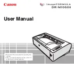
Demo Kit DK-SX5-B Components List
Model
Description
SX5-B
SX5 Safety Scanner
STP-M12D-406
Cordset, M12 D-Code to RJ45
Box with S22 Touch with In/Out Functions
Power Supply, 24 V, 1 A
•
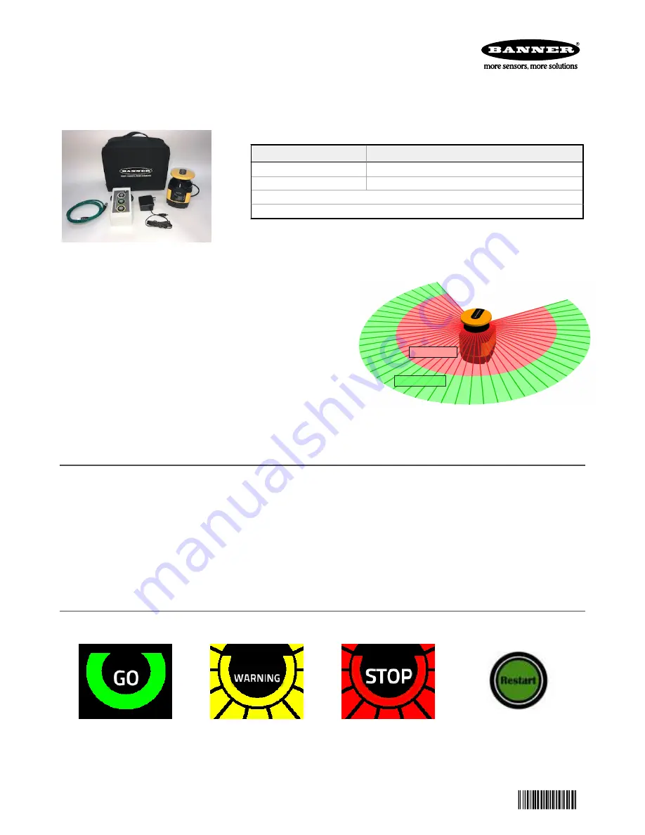
Two-dimensional laser scanner effectively protects personnel and
stationary and mobile systems within a user-designated area
•
Individually
define
up to six Safety Zones and two Warning Zones
using a PC
•
Safety Zone range of 5.5 meters at 70 mm resolution or 3 meters
at 40 mm resolution
•
Highly
flexible
Safety and Warning Zones can be set to match the
shape of the work area
•
275° sensing angle
•
Suitable for horizontal, vertical, and AGV applications
Warning Zone (WZ)
Safety Zone (SZ)
First Steps
1. Download the SX5soft software from www.bannerengineering.com and install on a computer.
2. Launch the software.
3. Connect the power jack of the power supply into the mating connection located at the top of the I/O box.
4. Connect the 8-in Euro-style connector of the I/O Box to the matching connector on the SX5 scanner.
5. Plug the power supply into a wall outlet.
6. Open the rubber dust cover at the front of the SX5 scanner and connect the Ethernet cable's 4-pin Euro-style connector.
Connect the RJ45 end to your computer.
We recommend using the USB-to-Ethernet adapter (not included with the kit). This allows you to have an adapter
configured
for
Ethernet communication with the SX5 and keep the computer's built-in Ethernet adapter available for other uses.
Review of Display
Typical display icons seen during normal set up for static operation, assuming that a Warning Zone and manual reset is
defined
within the
configuration.
All zones are clear
Warning zone interrupted
Safety zone interrupted
Waiting for a restart interlock
Display icons for diagnostic notes, warnings, and errors (19 icons possible)
SX5 Safety Scanner Demo Kit Setup Instructions
Original Document
209666 Rev. A
19 March 2019
209666