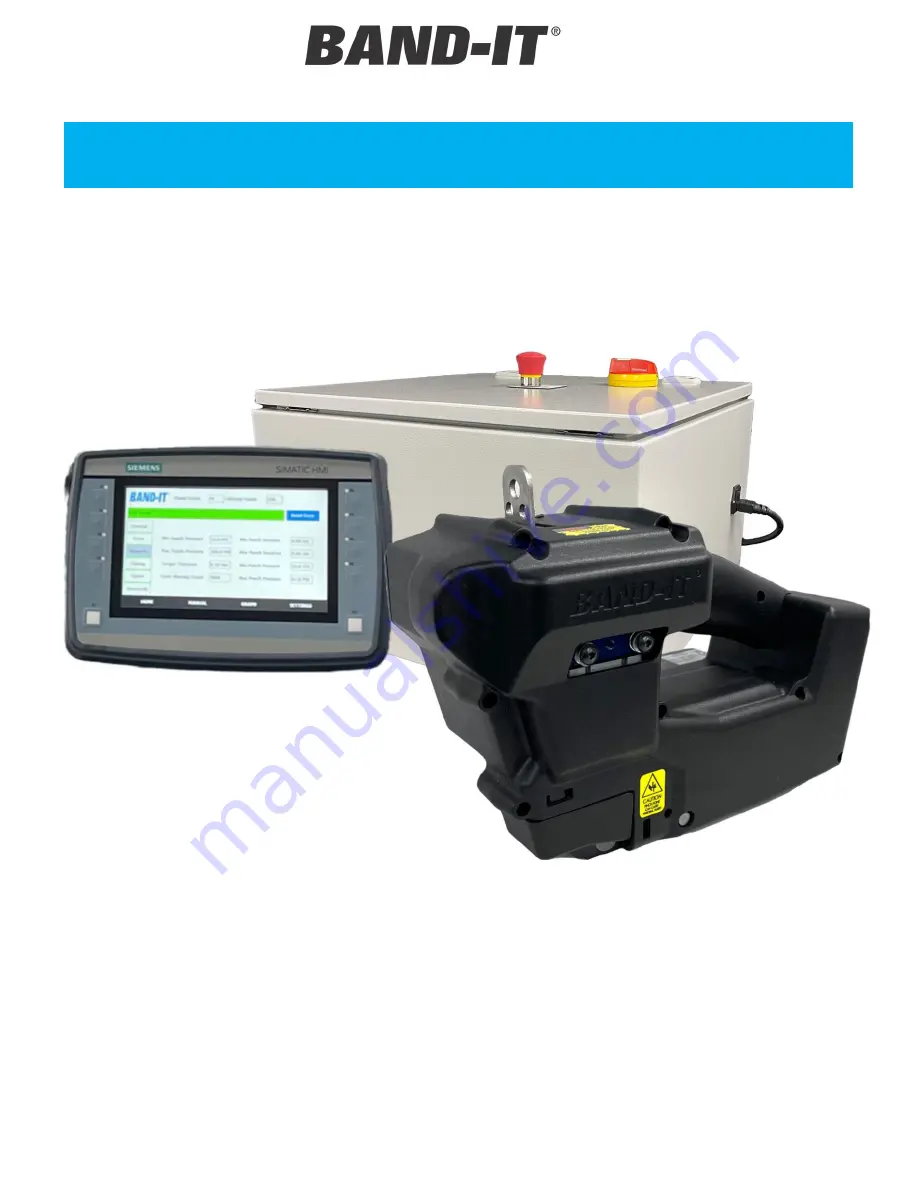
background image


User Manual 

IT8000 

3/8” Tie

-Lok® Data Tool 

Document #P80080 Rev. B 

© Copyright 

BAND-IT-IDEX, Inc. 2022 

All rights reserved 


All rights reserved 

BAND-IT-IDEX, Inc. 
A Unit of IDEX Corporation 
4799 Dahlia Street 
Denver, CO 80216-3070 USA 
P: 1-800-525-0758 


IT8000 

User Manual 


Original document 
(Not a translation) 

Summary of Contents for IT8000

Page 1: ... Tool Document P80080 Rev B Copyright BAND IT IDEX Inc 2022 All rights reserved BAND IT IDEX Inc A Unit of IDEX Corporation 4799 Dahlia Street Denver CO 80216 3070 USA P 1 800 525 0758 IT8000 User Manual Original document Not a translation ...

Page 2: ...QUICK START OVERVIEW 8 ENVIRONMENT 9 TRANSPORTATION STORAGE HANDLING 9 TOOL SETUP 10 OPERATING REQUIREMENTS 10 PART DESCRIPTIONS AND LOCATIONS 11 INSTALLATION TOOL DIMENSIONS 13 CONTROLLER ENCLOSURE DIMENSIONS 14 CONNECTING THE TOOL TO CONTROLLER 15 CONNECTING THE HMI TO CONTROLLER 16 AIR SYSTEM SETUP AND PRESSURE SETTINGS 17 AIR FLOW TIMING 18 FACTORY PROGRAM SETTINGS 31 SYNCING TOOL TO CONTROLLE...

Page 3: ... 3070 USA P 1 800 525 0758 HARNESS ROUTING 28 TOOL CLEARANCE REQUIREMENTS 29 SENSOR ACTIVATION 30 REMOTE ACTUATION 30 CUT OFF SIGNAL 30 SOFTWARE AND ELECTRONICS 32 HMI OVERVIEW 32 MAINTENANCE 39 MAINTENANCE SCHEDULE 39 LUBRICATION 40 TENSION WHEEL CLEANING 41 KNIFE REPLACEMENT 42 HEAD REPLACEMENT 43 PUNCH REPLACEMENT 44 TENSION AND BACKING WHEEL REPLACEMENT 45 TROUBLESHOOTING 46 ERROR CODES 49 ...

Page 4: ... to ensure fingers are not in the way of the clamp being applied o Maintain the tool by following the scheduled preventative maintenance interval provided in this document o Never use this product for anything other than its original intended purpose IMPORTANT o The object clamped and the 3 8 Tie Lok tie must be compatible with each other and the environment in which the final product will be used...

Page 5: ...he installation section before installing machine Do not operate machine with wet hands Please read this entire manual before unpacking setting up or operating this equipment Pay attention to all danger and caution statements Failure to do so could result in serious injury to the operator or other personnel or damage to the equipment SAFETY SIGNS High Voltage Risk of electric shock Pinch Point Ref...

Page 6: ...ng power to unit Unplug from wall or main enclosure Interlocking functions and features The tool is not intended to operate without guards in place The tool does not have any interlock functions or features that prevent operation if the guards are missing or enclosures are open It is the responsibility of the user to provide safety interlocks if required Securing machine for safe maintenance The t...

Page 7: ... Unit of IDEX Corporation 4799 Dahlia Street Denver CO 80216 3070 USA P 1 800 525 0758 PRODUCT SAFETY LOCATIONS Warning Do not place fingers hands or any body parts under the cutting head while tool is running Warning Do not place fingers hands or any body parts near the outlet of the tail eject while tool is running Figure 2 Figure 3 ...

Page 8: ... OVERVIEW 1 Connect data and motor cable to tool Page 15 Note Ensure controller power and air are off before connecting to the tool Page 16 2 Connect data cable to controller Page 16 3 Connect air harness to tool Page 15 and controller Page 17 Fig 20 4 Connect HMI touchscreen to controller page 16 5 Connect external regulator to controller page 16 6 Connect air hose to external controller regulato...

Page 9: ...r lifting and moving heavy objects Normal operating conditions are defined as For Indoor Use ONLY Temperature range from 5 C to 40 C 41 F to 95 F Max relative humidity 80 for temperatures up to 31 C 88 F decreasing linearly to 50 at 40 C 104 F Conforms to Applicable RATED POLLUTION DEGREE 1 Correct illumination for safety of operator ISO 8995 89 Avoid using the tool near equipment with strong EMI ...

Page 10: ...e 2 Clamp Type BAND IT 3 8 Tie Lok Tie Series Operation Air Requirements 80 PSI 552 kPa Clean dry compressed air Air Flow Rate 0 25 CFM 7 1 L min Do not exceed pressure listed on regulator assembly Power requirements 110 230 Volts 50 60 Hz Grounded AC 4 A Max Human Machine Interface HMI Programmable Color Touchscreen Emergency Stop Application of emergency stop button will stop electric motor and ...

Page 11: ... USA P 1 800 525 0758 PART DESCRIPTIONS AND LOCATIONS Clamp Cylinder Pinch Arm Upper Band Guide Lower Band Guide Backing Wheel Punch Punch Holder Trigger Link Tension Wheel Punch Cylinder Trigger Trigger Cylinder Cut Straight Link Tool Head Tangency and Buckle Sensors Cut off Cylinder Frame Cut off Cylinder Mount Plate Serial Number Located here Drive shaft Knife Cutter Arm Cut Link Figure 5 Figur...

Page 12: ...ev B Copyright BAND IT IDEX Inc 2022 All rights reserved BAND IT IDEX Inc A Unit of IDEX Corporation 4799 Dahlia Street Denver CO 80216 3070 USA P 1 800 525 0758 PART DESCRIPTIONS CONT Right Cover Pneumatics Cover Head Cover Handle Cover Left Side Cover Figure 6 ...

Page 13: ...Data Tool Document P80080 Rev B Copyright BAND IT IDEX Inc 2022 All rights reserved BAND IT IDEX Inc A Unit of IDEX Corporation 4799 Dahlia Street Denver CO 80216 3070 USA P 1 800 525 0758 INSTALLATION TOOL DIMENSIONS Figure 7 Figure 8 ...

Page 14: ...BAND IT IDEX Inc 2022 All rights reserved BAND IT IDEX Inc A Unit of IDEX Corporation 4799 Dahlia Street Denver CO 80216 3070 USA P 1 800 525 0758 CONTROLLER ENCLOSURE DIMENSIONS Figure 9 The controller box is designed to be mounted with 4 9 16 holes on the back mounting plate ...

Page 15: ...e interface do not attempt to force a plug into a connector if the receptable does not match or the key is misaligned Connect the motor cable to the motor Align the two arrows on cable and connector and then rotate a quarter turn fig 11 The tool includes an air harness with six 6 35mm outside diameter tubes pre assembled to quick connect ends Attach one end to the controller and the other end to t...

Page 16: ...ulator has two connections that must be connected Fig 17 Each electrical connector has a unique interface do not attempt to force a plug into a connector if the receptable does not match or the key is misaligned The controller has inputs for a Pass Fail cutoff signal and remote actuation to operate the tool hands free These do not need to be connected to run the tool in normal operation The contro...

Page 17: ...h Extend line Fig 19 The punch must be extended to read the pressure The punch pressure reading is shown on the manual screen pg 33 The regulators are adjusted independently Note that the HMI pressure limits may need to be updated as well pg 36 but the pressure cannot be adjusted in the HMI The regulator has a 3 8 OD push to connect fitting on it If a different style of fitting is preferred to con...

Page 18: ...will wait for the next trigger press to eject scrap Note Regardless of the setting the scrap will have to be pulled out by hand See HMI settings to change the setting pg 35 Event description Tool ready for next tie Engage gripper Tension clamp engage punch cylinder Actuate trigger to dimple Retract punch Reset trigger Cut off Eject Timing duration At rest Entire duration of tensioning tie and ejec...

Page 19: ...ness to new tool 6 Release E stop or turn controller back on Ensure Door Latch is in the On position 7 Go to settings screen General tab 1 Select Change Tool 2 Select the serial number 3 Type in the new tool s serial number 4 Select Enter 5 Enter Clamp Count And Tool Cycle Count 6 Select Done 8 Input tool settings If changing application 1 Set system pressure and punch pressure Refer to settings p...

Page 20: ...will stop tensioning and open the gripper 7 The tool will continue to run until it reaches the desired tension At this point the tool will hold tension but not fire the punch until the tool is moved tangent to the work surface 8 Once the tangency and buckle sensors have been activated the tool will complete the punch and cut cycle 9 Data will be logged onto the controller and can be downloaded to ...

Page 21: ...Avoid sharp corners add largest radius possible on square corners Fig 29 Tie Lok can be installed on flat surfaces Do not install clamps on tapered surfaces or on tube bends Fig 29 Tie Lok advised min installed diameter is 1 The buckle area of the shield must be free of voids and wrinkles For specific questions contact your BAND IT IDEX account manager Locking Dimple The IT8000 forms a locking dim...

Page 22: ...cer The tool needs to be located directly above the clamp location if using a balancer as shown below Figures 32 33 The balancer must support the weight of approximately 10 lb The tool comes with a hanger loop to mount to a balancer For more complex installations there are three mounting holes on the side See page 25 for more information about controlling the tool in roll and yaw Note that the cen...

Page 23: ...slide rail or swing arm is required to move between the ties Always allow the tool to hang directly above the installation Pulling the tool at an angle will cause increased strain on the operator Figures 35 36 are an example of a weight balancer that can rotate in all 3 axis Depending on the application the harness can either be routed up the balancer or at ground level For technical drawings or f...

Page 24: ... most ergonimic design we recommend moutning the tool on an articulating arm or fixture Articulating Arms Three 10 32 mounting holes are provided to attach the IT8000 to an articulating arm The arm must be able to support approximately 10 lb in addition to any brackets installed to the tool See page 25 for more information about controlling the tool in roll and yaw See Figures 39 40 for two exampl...

Page 25: ... to the work piece A minimum of 30 of rotation is required for the tool to operate but 120 is recommended The tool should be allowed to rotate both forwards and backwards from the tangent point the buckle is expected to be placed See Figure 41 for the minimum rotation away from the buckle Yaw is typically required if the tool is installing more than one clamp especially if the tool is on a swing a...

Page 26: ...A P 1 800 525 0758 Figure 43 Figure 44 Figure 45 CENTER OF GRAVITY The center of gravity CG is shown below in relation to the hanger loop and mounting holes The closer the rotational point is to the CG the easier the rotation will be If roll is required for the application centering the rotation around the roll axis is the top priority Followed by pitch and then yaw 57 4 CG Icon 55 9 4 1 118 6 48 ...

Page 27: ...rporation 4799 Dahlia Street Denver CO 80216 3070 USA P 1 800 525 0758 Figure 46 Figure 49 Figure 48 Figure 47 MOUNTING EXAMPLES Figures 46 49 are an example of an articulating arm and mounting bracket that can rotate in all 3 axis For technical drawings or further information about this design contact your account manager Yaw Axis Pitch Axis Roll Axis ...

Page 28: ...that the center of gravity is behind the hanger bracket For best performance the pivot point should be located on the CG not directly on the hanger bracket HARNESS ROUTING It is recommended to run the pneumatic electrical harness down the length of the articulating arm This will keep the harness out of the way and protect it from being damaged Ensure that there is enough slack in the harness to no...

Page 29: ...D IT IDEX Inc A Unit of IDEX Corporation 4799 Dahlia Street Denver CO 80216 3070 USA P 1 800 525 0758 TOOL CLEARANCE REQUIREMENTS Minimum Clearance Requirements A Channel Height max 0 25 6 4mm B Head Width min 0 85 21 6mm C Centerline distance to flange min 1 00 25 4mm D Tool Width 5 50 139 7mm Figure 53 A B C Figure 54 D ...

Page 30: ...nector is located next to the remote actuation on the controller If using the Mencom yellow cable measure the signal across the white and blue wires Contact BAND IT IDEX for recommendations on how to setup the cut off signal Note the tangency sensor is only activated on metallic objects If installing on plastic or rubber the sensor will need to be disabled To ensure proper sensor activation the ch...

Page 31: ...orque 40 Setpoints Min Supply Pressure 75 PSI Max Supply Pressure 85 PSI Torque Tolerance 0 10 in lbf Min Punch Duration 0 5 ms Max Punch Duration 5 0 ms Min Punch Pressure 63 PSI Max Punch Pressure 67 PSI Timing Line Up Tool Timeout 10 s Position Sensors Debounce 0 01 s Cut Off Delay 0 05 s Punch Extend Duration 0 10 s Auto Eject Duration 0 5 s Cut Retract Delay 0 20 s Speed Max Tension Speed 50 ...

Page 32: ...ure reading off input regulator controls the non punch cylinders Punch Pressure Pressure reading inside tool controls only the punch cylinder Motor Torque Instantaneous motor torque Punch Max Duration Max duration for the punch velocity sensor before giving an error Punch Duration Actual punch duration of the previous cycle Motor Torque Target target final torque Serial Number Serial number of the...

Page 33: ...l not install a clamp in this state An LED on the F1 button will blink to alert you that the tool is still in manual mode Pull Band Rotates the motor to pull the tie into the tool The motor runs at the speed indicated next to Torque Move Release Rotates the motor to push the tie out of the tool The motor runs at the speed indicated next to Torque Move Torque Move Rotates the motor to pull the tie ...

Page 34: ...s where the Punch and Cut happen All data shown on the graph screen is stored in the PLC When switching to the graph screen the HMI will auto populate with the most recent cycle When on the graph screen Refresh must be pressed Graph populating takes around 1 minutes There is a green status bar below the Reset Error button that shows graphing progress Punch Time History Punch time history can be se...

Page 35: ...of installs Copy Log to USB transfers the selected file to USB flash drive if installed If a duplicate file name is already on a USB stick the current file will be over written with the latest version Enable Contact Switch double tap On Off switch to enable or disable the tangency and buckle sensors Eject Mode Auto Activates the motor for a preset time after the cut to eject the tail Manual does n...

Page 36: ...scode to clear an error Error Codes to Require Passcode Number of errors in a row before the passcode is needed Settings Screen Setpoints Min Max Supply Pressure Prevents tool from operating outside the settable supply pressure range Min Max Punch Pressure Prevents tool from operating outside the settable punch pressure range Min Max Punch Duration Settable range of punch duration Tool will give e...

Page 37: ...on Sensors Debounce How long the proximity sensors need to be in position before the tool completes the cycle Cut off delay Delay between punch and cut Punch Extend Duration Time the punch cylinder is extended Auto Eject Duration Time the tool runs after cut if automatic ejection is enabled Cut Retract Delay Time the cut cylinder is extended Settings Screen Speeds Max Tension Speed Speed of tool d...

Page 38: ... Acknowledgement Password Requires a password to Reset Error Optional Settings Administrator Password Password required to access the SETTINGS tab Password screen will pop up if Log In is attempted on the HOME screen Auto logout is available for both passwords and the time limit before the logout happens is adjustable HMI Physical Buttons The HMI Screen has physical buttons to the sides of the tou...

Page 39: ...em Do not remove factory applied lubrication from inside tool unless performing a thorough maintenance procedure and then replacing with clean lubricant immediately Follow preventative maintenance and parts replacement instructions at appropriate service intervals For maintenance beyond what is described in this manual contact BAND IT Components Recommended Service Recommended Interval Page Ref Ba...

Page 40: ...wheel pin through the grease port on side of tool L8503 or similar needle type grease fitting is required Lubricating the knife requires partially sliding it out see page 42 for instructions To increase time between grease it is recommended to grease the involute linkage as well Grease Port Knife Important Prior to any maintenance or disassembly be sure to disconnect all power sources to the tool ...

Page 41: ...sure the backing wheel and pin do not slide out with the pinch arms removed 2 Enter manual mode to drive the tension wheel for a few revolutions with the wire brush 1 4 brush width 3 pressed firmly up into the rotating wheel 3 During reassembly re center the tension wheel between the pinch arms and the band guide lined up on the pinch arms to allow for proper re assembly Important Prior to any mai...

Page 42: ...e Remove the E Clips 2 on the non motor side only Push the 2 pins 3 down far enough to allow the linkage 4 to swing out Remove the knife 5 Apply a film of grease to the new knife and pins and reassemble using new E clips if needed Replacement Knife Kit Part Number H80935 Note The cutter knife has only one cutting edge This edge must be properly oriented as shown when installing Important Prior to ...

Page 43: ... Disconnect the sensor cable and remove the head 6 Apply a film of grease on the pins and knife and reassemble Ensure that the upper pin goes through the trigger assembly linkage 7 Fig 74 Apply Blue Loctite to screws Only pull on gray cable jacket when connecting head sensor The pneumatics cover or side cover may need to be removed to reconnect the head sensors or to insert the pins Replacement He...

Page 44: ...PUNCH REPLACEMENT Remove the head as shown on page 43 Extend the cylinder by pulling on the punch 1 until the punch holder is visible Punch the spring pin 3 32 Dia 2 out Reassemble Always using a new spring pin 2 when replacing the punch Replacement Punch Kit Part Number H80925 1 2 Important Prior to any maintenance or disassembly be sure to disconnect all power sources to the tool and discharge p...

Page 45: ... key 8x 2 Remove the clevis pin 3 and drop the pinch arms Remove M4 screws 3mm key 3x 4 Remove Motor assembly 5 The gripper wheel can now be pulled out of the tool 6 To remove the backing wheel push the pin out 7 and remove the wheel 8 Reassemble applying blue Loctite to M4 screws Replacement Tension Kit Part Number H80915 1 2 3 4 5 6 7 8 Important Prior to any maintenance or disassembly be sure t...

Page 46: ... is tight Check for foreign object present or other obstructions Pre set tension is not reached Tension Wheel slipping Inspect clamp tail for evidence of slipping Clean Tension and Backing Wheels with wire brush If slipping persists replace Tension and or Backing Wheel Loss of air pressure to Clamp cylinder 80 PSI Verify that air source and fittings are pressurized unobstructed and not leaking Dri...

Page 47: ...structions Clamp buckle located above void or opening Be sure to locate buckle on fully supported surface Object being clamped is hand held Small light weight objects clamped must be properly held in place in a fixture Object being clamped is soft with thick wall Adjust the Punch pressure higher and verify dimple depth Be sure that object clamped is held in place and locked down in fixture Adjust ...

Page 48: ...ber of pins on individual connections and observe keyed orientation of the connectors All threaded sleeves on connectors must be fully assembled and secured Power entry plug switch or door latch turned Off Check switch status Internal Circuit Breaker s tripped to Off position Check to make sure all Circuit Breakers are in the On position located inside the Electrical Control box Tool does not acti...

Page 49: ...s will begin with a 3 Error Messages These do not stop the sequence and the tool can complete an installation when these occur but they may mean that the tool has not installed the band to the right specifications Error messages will persist when the Enable Error Bypass setting is not checked These message types will increment the Error Codes counter All error messages begin with a 2 Critical Alar...

Page 50: ...amaged punch cylinder 213 Parameters Not Passed Torque Out of Tolerance This error will occur after a completed cycle if the measured motor torque is outside of the allowed range set on the HMI for the set monitoring period The torque is monitored from the point where it reaches the torque tolerance band and through tightening until after the punch operation Possible Cause Tolerance settings too t...

Reviews: