


Reviews:
No comments
Related manuals for SMARTCAMERA IO

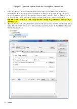
S2
Brand: Zenza Bronica Pages: 29

E-1 - Digital Camera SLR
Brand: Olympus Pages: 2

LPC Series
Brand: Okina Pages: 3
Z3
Brand: Z-EDGE Pages: 4

F3102
Brand: Zavio Pages: 31

SK6288GKOC-L
Brand: Schäfter+Kirchhoff Pages: 32

4GPTZ675AI
Brand: LINOVISION Pages: 15
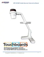
QPC 30M
Brand: Qomo Pages: 10

E27SX1
Brand: CamnSmart Pages: 10

NGC-7522R
Brand: Navaio Pages: 58

RAC-04
Brand: Rac Pages: 16

VISTA XLT
Brand: Watchguard Pages: 32

Digital signage LDV43-SAI200
Brand: Dahua Technology Pages: 38
VC-54B
Brand: E-SYSTEM Pages: 4

DIC-5430DV
Brand: D-MAX Pages: 16

DP21-SAL
Brand: Olympus Pages: 2

Optio MX4
Brand: Pentax Pages: 68

IntelliSHOT-M
Brand: VADDIO Pages: 76


