Baker Hughes Masoneilan SVi 1000, Quick Start Manual
The GE Masoneilan SVi 1000, an advanced control valve, is equipped with cutting-edge technology for precise and efficient process control. Enhancing its usability is the user-friendly Instruction Manual available for free download from manualshive.com. Get the most out of your SVi 1000 experience with this comprehensive manual at your fingertips.
Share
Download


Reviews:
No comments
Related manuals for Masoneilan SVi 1000

TZIDC
Brand: ABB Pages: 4

TZIDC
Brand: VAC Pages: 40

TZIDC
Brand: ABB Pages: 48

TZIDC-200
Brand: ABB Pages: 34

TZIDC-200
Brand: ABB Pages: 40

TZIDC-200
Brand: ABB Pages: 68

PositionMaster EDP300
Brand: ABB Pages: 52

Masoneilan 4700E
Brand: Baker Hughes Pages: 12

Masoneilan SVI FF
Brand: Baker Hughes Pages: 22

4785
Brand: Samson Pages: 78

D400
Brand: VAC Pages: 48

D400
Brand: VAC Pages: 71

Masoneilan SVI3
Brand: Baker Hughes Pages: 14

TT-100
Brand: Bancroft Pages: 12

EP100
Brand: EBRO ARMATUREN Pages: 23

PSD4 Series
Brand: halstrup-walcher Pages: 5

3761
Brand: Samson Pages: 28
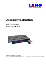
LHT Series
Brand: Lang Pages: 58


