background image

All information contained within this publication is based on the 

latest product information at the time of publication. Due to 

constant improvements in the design and quality of production 

components, some minor discrep ancies may result between the 

actual vehicle and the information presented in this publi cation.
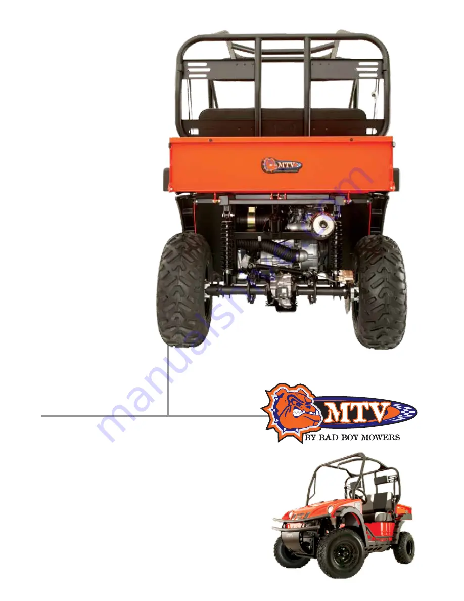
Model 1500

(Gas Powered)

Multi-Terrain Vehicle 

(MTV)

Service Manual

Summary of Contents for 1500

Page 1: ...ion at the time of publication Due to constant improvements in the design and quality of production components some minor discrep ancies may result between the actual vehicle and the information prese...

Page 2: ...test product information at the time of publication Due to constant improvements in the design and quality of production components some minor discrep ancies may result between the actual vehicle and...

Page 3: ...ecting and adjusting the Bad Boy MTV Chapter 1 Page 4 covers general information and troubleshooting diagnosis Chapter 2 Page 24 covers the service maintenance information and special tools manual Cha...

Page 4: ...5 ENGINE REMOVAL 6 CYLINDER HEAD VALVE 7 CYLINDER PISTON 8 V TYPE BELT DRIVING SYSTEM 9 FINAL DRIVING MECHANISM 10 ALTERNATOR STARTING CLUTCH 11 CRANKSHAFT CRANKCASE 12 COOLING SYSTEM 13 FRONT BRAKE...

Page 5: ...PAGE 5 Serial Number on MTV PIN Number Located under seat on passenger side...

Page 6: ...unconsciousness and even result in death Gasoline Gasoline has a low ignition point and is an explosive material Work in a well ventilated area no flame or spark should be allowed in the work place or...

Page 7: ...n your eyes wash immediately with water and then see a doctor Brake shoe quick tip Do not use an air hose or a dry brush to clean components of the brake system use a vacuum cleaner or equivalent to a...

Page 8: ...tion to O rings or oil seals because most cleaning agents have an adverse effect on them Never bend or twist a control cable to prevent cable damage or premature wear Old rubber parts may become deter...

Page 9: ...he groove with grease install the oil seal with the name of the manufacturer facing outside and check the shaft on which the oil seal is to be installed for smoothness and for burrs that may damage th...

Page 10: ...tery posts have to be greased after connected the cables Make sure that the battery post caps are placed in their proper position after the battery posts have been serviced When separating a connector...

Page 11: ...her pull too tight nor have excessive slack Protect wires and wire harnesses with electrical tape or tube to protect them from contact with a sharp edge or corner Thoroughly clean the surface where ta...

Page 12: ...cement 403 1 Compression Ratio 9 2 1 Maximum HorsePower 28 6500rpm Maximum Torque 18 8 ft lbs 4000rpm Ignition C D I Starting System Electrical Starter with backup recoil starter Air Filtration Paper...

Page 13: ...Solid Particulate CO Below 7 0g km HC Below 1 5g km NOx Below 0 4g km E E C None P C V None Catalytic Reaction Control System None Brake System Front Disk 180mm Rear Disk 200mm Performance Max Speed...

Page 14: ...er bolt 2 6 7 10 ft lbs Cylinder head cover bolt 4 6 7 10 ft lbs Cylinder head stud bolt inlet pipe 2 6 7 10 ft lbs Cylinder head stud bolt EX pipe 2 8 17 21 ft lbs Air inject pipe bolt 4 6 7 10 ft lb...

Page 15: ...t 2 14 36 Rear wheel nut 8 10 30 Engine hanger nut 4 12 34 Rear axle holder bolt 4 12 50 Drive gear bolt 2 10 34 Driven gear nut 4 10 34 Swing arm pivot bolt 1 14 50 Front suspension arm nut 4 10 36 F...

Page 16: ...sed fuel tank cap Check and Adjustment Remove spark plug install it into spark plug cap and perform a spark test against engine ground Check to make sure it sparks properly IF SPARK PLUG IS FUNCTIONIN...

Page 17: ...too high Malfunction of throttle valve operation Throttle valve opening too wide Check and Adjustment Remove carburetor and connect a hose onto fuel inlet Then blow air into the hose Check and Adjust...

Page 18: ...eaked Valve deterioration Seized piston ring Check and Adjustment Check to see if carburetor jet is clogged Fault Condition Clogged Probable Causes Remove foreign object Check and Adjustment Remove sp...

Page 19: ...ition timing using ignition lamp Fault Condition Abnormal Probable Causes Incorrect ignition timing malfunction of CDI or AC alternator Check and Adjustment Adjust the air screw of the carburetor Faul...

Page 20: ...in spark plug leads Malfunction of main switch D Engine runs Sluggish at high speeds Check and Adjustment Check ignition timing Fault Condition Abnormal Probable Causes Malfunction of CDI Malfunction...

Page 21: ...ves forward or jumps suddenly rear wheel rotating as engine in running Probable Causes Clutch weights spring broken Clutch outer stuck with clutch weights Connection parts in clutch and shaft worn out...

Page 22: ...e G Loss of Power Check and Adjustment Raise wheels off ground and spin by hand Fault Condition Abnormal don t spin freely Probable Causes Brake dragging Damaged wheel bearing Wheel bearing needs lubr...

Page 23: ...ck spark plug Fault Condition Fouled or discolored Probable Causes Clean the spark plug Spark plug is incorrect heat range Check and Adjustment Check engine for overheating Fault Condition Overheating...

Page 24: ...eaner Page 29 Spark Plug Page 30 Valve Clearance Page 30 Carburetor Idle Speed Adjustment Page 31 Ignition System Page 32 Cylinder Compression Pressure Page 32 Drive Belt Page 33 Brake System Disk Bra...

Page 25: ...arance of throttle valve N A 1 3 mm Spark plug Type Type NGK CR7E Spark plug Gap 0 7 0 8 mm F Mark in idling speed N A BTDC 20o 1500 rpm Full timing advanced N A BTDC 51o 6200 rpm Idling speed N A 150...

Page 26: ...the MTV is operated on dusty roads or in a Heavily polluted environment 2 Maintenance should be performed more often if the MTV is frequently operated at high speed and after the MTV has accumulated...

Page 27: ...n key to run setting Do not modify shift linkage while engine is running Verify heim joint is fully threaded in and jam nut is securely fastened Only a few threads should be showing as in picture Brea...

Page 28: ...everse indicator light on the dash panel will illuminate Tighten rear shift bracket nut snugly against shift cable bracket while ensuring the engine shift lever is still in the reverse position Tighte...

Page 29: ...t if deteriorated twisted or damaged Lubricate the cable if operation is not smooth Measure the throttle pedal free play Remove rubber boot loosen fixing nut and then adjust it by turning the adjustme...

Page 30: ...nd adjustment must be performed when the engine temperature is below 350 celsius or 950 Fahrenheit Remove cylinder head cover Turn camshaft bolt in Clockwise direction and make the T mark on the camsh...

Page 31: ...speed Warm up the engine for around 10 minutes and then conduct this adjustment 1 Connect the tachometer onto engine 2 Adjust the throttle valve stopper screw and let engine runs in 1500 100 rpm 3 In...

Page 32: ...rect check CDI set pulse rotor and pulse generator Replace it if malfunction of these parts is found Cylinder Compression Test Warm up engine Turn off the engine Remove the seat Remove spark plug cap...

Page 33: ...LOWER limit add brake fluid to UPPER limit Also check the brake system for leaking if low brake level found Air Bleed Operation Connect a transparent hose to draining valve Hold the brake pedal and o...

Page 34: ...heck the brake lining condition Replace the lining if the brake lining wear limitation groove close to the brake disc Brake Light Switch Starting Inhibitor Switch Make sure that electrical starter can...

Page 35: ...l Measure tire thread depth from tire central surface Replace the tire if the depth does not come with following specification Front tire 25 Rear tire 28 Nuts Bolts Tightness Perform periodical mainte...

Page 36: ...90 hypoid gear oil Oil Capacity 300 c c Remove the under cover Place an oil pan below the differential set case Filler Nut Remove drain bolt filler nut and drain oil out Tighten the drain bolt to spec...

Page 37: ...t Remove the filler cap Drain oil Tighten the drain blot Remove the oil check bolt Pour the specified oil through the filler hole until the oil lever reaches bottom of the hole Tighten the oil level b...

Page 38: ...PAGE 38 SERVICE MANUAL CHAPTER 3 LUBRICATION SYSTEM Mechanism Diagram Page 38 Troubleshooting Page 39 Engine Oil Page 40 Engine Oil Strainer Clean Page 40 Oil Pump Pages 41 42 Mechanism Diagram...

Page 39: ...l Pump Inner rotor clearance 0 15 0 20 Clearance between outer rotor Oil pump and body 0 15 0 20 0 25 Clearance between rotor side and body 0 04 0 09 0 12 Torque value Torque value oil filter 10Ft Lbs...

Page 40: ...lue 17 20 ft lbs Engine Oil Strainer Clean Drain engine oil Remove oil strainer cap Clean oil strainer Check if O ring can be re used Install oil strainer cap Torque value 7 ft lbs Engine oil capacity...

Page 41: ...ION The clutch shoe nut has left hand threads Remove the snap ring Remove the washer Remove the oil pump driver gear Remove the pin Remove the washer Make sure that pump shaft can be rotated freely Re...

Page 42: ...Install inner and outer rotors into the pump body Align the indention on driving shaft with that of inner rotor Install the oil pump shaft and roller Install the oil pump cover and fixing pins proper...

Page 43: ...strictly prohibit flame when working with gasoline CAUTION Do not bend throttle cable Damaged throttle cable will make MTV unstable When disassembling fuel system parts pay attention to O ring positi...

Page 44: ...Incorrect idle speed Malfunction of carburetor Dirty fuel Intermittently misfire under acceleration Malfunction of ignition system Late ignition timing Malfunction of ignition system Malfunction of ca...

Page 45: ...Installation Install in reverse order of removal procedures Air Cut Off Valve Disassembly Remove air vent hoses Remove fuel hose Remove vacuum hose Remove air cut off valve cover 2 screws spring and v...

Page 46: ...mounting screws and remove float chamber cover Remove the screw float pin float and float valve Inspection Check float valve and valve seat for damage blocking Check float valve and seat face for wea...

Page 47: ...ment screw turn it all the way down and note the number of turns Do not turn adjust screw forcefully to avoid damaging valve seat face Assembly Install main jet needle jet holder needle jet slow jet a...

Page 48: ...ded Note the number of turns it takes to screw it all the way in for ease of installation Use a tachometer when adjusting engine RPM Screw in air adjustment screw gently then back up to standard turns...

Page 49: ...the seat 2 Open the front cover 3 Remove tank clamps 4 Disconnect fuel lines 5 Remove fuel unit FOR FULL FRONT ASSEMBLY DRAWING CHECK LAST 2 PAGES OF CHAPTER 4 Carburetor Hose Routing Fuel Pump Fuel V...

Page 50: ...ve pulley drive belt clutch and movable drive face assembly Start motor AC Generator oil pump and start one way clutch Crankcase RH cover Clutch housing assembly Directional clutch Clutch assembly Ite...

Page 51: ...g steps Reinstall the engine by reversing the removal procedure Before removal the engine drain all engine oil Remove the seat Remove the seat bracket Remove the battery negative post Remove the batte...

Page 52: ...RVICE MANUAL Engine Removal Remove the signal generator lead wire connector and generator lead wire connector Connectors Remove the spark plug cap Cap Remove the exhaust pipe Bolt Remove the front and...

Page 53: ...PAGE 53 Remove the front shaft bolts 6 in total Remove the engine mounting bolts and nuts Remove the engine mounting bracket Front engine mount Rear engine mount Rubber Isolator...

Page 54: ...l the engine in the reverse order of engine removal CAUTION The engine mounting nuts are self locking once the nut was been removed it is no longer of any use Be sure to use new nuts For every time en...

Page 55: ...ndard torque Apply sealant to the front propeller shaft flange coupling bolts Torque value Tighten them to the standard torque Front and rear propeller shaft flange coupling bolt 32 5 ft lbs Exhaust I...

Page 56: ...Exhaust pipe nut 16 5 ft lbs Connector bolt 16 5 ft lbs Muffler mounting bolt 16 5 ft lbs Exhaust pipe nut Apply sealant to the muffler mounting bolt and also to the muffler fixed bolts Tighten bolts...

Page 57: ...PAGE 57...

Page 58: ...on Page 59 Troubleshooting Page 60 Cylinder Head Removal Page 60 61 Cylinder Head Inspection Page 63 Valve Stem Replacement Page 64 Valve Seat Inspection and Service Page 65 66 Cylinder Head Reassembl...

Page 59: ...Exhaust 0 15 0 02mm 0 050 Item Compression Pressure Camshaft Height of camlobe ID of valve rocker arm OD of valve rocker arm Cylinder Head Warpage OD of valve system ID of valve guide Valve seat width...

Page 60: ...ment Burnt or bent valve Improper valve timing Valve spring damage Valve carbon deposit 2 Cylinder head Cylinder head gasket leaking or damage Cracked cylinder 3 Piston Piston ring worn out High compr...

Page 61: ...r the cam chain tensioner Loosen 2 bolts and then remove tensioner Remove thermostat 2 bolts Remove spark plug Remove the nuts of cylinder head 4 nuts Remove cylinder head cover 3 bolts Remove fix sta...

Page 62: ...ot damage the mating surfaces of cylinder and cylinder head Do not allow gasket material to fall into crankcase when cleaning Use a valve cotter removal assembly tool to press the valve spring and the...

Page 63: ...wear or damage Service Limit Replace when it is less than 12 080 mm Rocker Arm Shaft Measure the O D of the cam rocker arm shaft and cam rocker arm Service Limit Replace when it is less than 11 936 mm...

Page 64: ...Otherwise the cylinder head may be deformed Wear gloves to protect your hands when heating Valve guide driver 5 0mm Hold the cylinder head and then press out old valve guide from combustion chamber si...

Page 65: ...lve and check its contact face Valve seat inspection If the valve seat is too wide narrow or rough it needs correcting Valve seat width Service limit 1 6mm Check the contact condition of valve seat Va...

Page 66: ...alve seat with 60 cutter Then grind the valve seat to specified width Valve Seat Inspection and Service After the valve seat has been ground coat valve seat surface with emery and then grind surface C...

Page 67: ...new cylinder head gasket onto the cylinder CAUTION Do not damage the mating surfaces of cylinder and cylinder head Avoid gasket materials falling into crankcase Install 4 washers and tighten 4 bolts...

Page 68: ...Make sure timing marks are matched Install the lock washer so that it is covering the locating pin Bend up the washer tongue positively to lock bolts Align the line A on the generator rotor with the i...

Page 69: ...lve clearance has been adjusted to standard value hold adjustment bolt and then tighten the Adjustment nut Standard Value IN 0 10 0 02 mm EX 0 15 0 02 mm Start the engine and make sure that engine oil...

Page 70: ...DER PISTON Mechanism Diagram Page 70 Precautions in Operation Page 71 Troubleshooting Page 71 Cylinder Piston Removal Page 72 73 Piston Ring Installation Page 74 Piston Installation Page 74 Cylinder I...

Page 71: ...onnecting rod small end OD of piston 2nd Clearance between piston and cylinder ID of piston pin boss Item Cylinder Piston Piston Ring Clearance between piston rings Ring end gap Troubleshooting Low or...

Page 72: ...rom the two matching surfaces of cylinder and crankcase CAUTION Soak gaskets in solvent so that the residue can be removed more easily Inspection Check the inner diameter of cylinder for wear or damag...

Page 73: ...diameter of piston pin Service Limit 19 96 mm Measure the inner diameter of connecting rod small end Service Limit 20 065 mm Measure the inner diameter of piston pin hole Service Limit 20 02 mm Calcul...

Page 74: ...ure that all piston rings can be rotated freely after installed Clean up all residue and foreign materials on the matching surface of crankcase CAUTION Soak gaskets in solvent so that the residue can...

Page 75: ...iston and piston rings with Engine oil Care needs to be taken when installing piston into cylinder Press piston rings in one by one CAUTION Do not push piston into cylinder forcefully because piston a...

Page 76: ...APTER 8 V BELT DRIVE SYSTEM Mechanism Diagram Page 76 Precautions in Operation Page 78 Troubleshooting Page 78 Clutch Cover Page 79 Drive Belt Page 79 Drive Face Page 80 Clutch Outer Driven Pulley Pag...

Page 77: ...985 mm 40 935 mm ID of driven face 45 000 45 035 mm 45 600 mm Weight of weight roller 13 300 13 700 g 12 800 g Torque value Special Service Tools Drive face nut 55 ft lbs Clutch spring compressor Clut...

Page 78: ...bearing s inner ring with fingers Ensure bearings can be turned smoothly and silently and bearing outer ring is mounted in cover tightly If bearing rotation is uneven noisy or loose then replace it D...

Page 79: ...gram shown Service Limit 27 0 mm Replace the belt if exceeds the service limit CAUTION Use only genuine parts for replacement The surfaces of drive belt or pulley must be free of grease Clean up all g...

Page 80: ...f weight rollers are worn out or damaged the centrifuge force will be affected Check rollers for wear or damage Replace as necessary Measure each roller s outer diameter Replace if it exceeds the serv...

Page 81: ...r Tighten nut to specified torque Torque value 55 ft lbs Install belt cover Clutch Outer Driven Pulley Disassembly Remove drive belt and driven pulley Install clutch spring compressor onto the pulley...

Page 82: ...er 45 60 mm Installation of Clutch OUTER Driven Pulley Assembly Install new oil seal and O ring onto movable driven face Apply with specified grease to lubricate the inside of movable driven face Inst...

Page 83: ...arate the driven output rear shaft and front shaft Remove the c ring from the universal joint assembly Remove the driven output front shaft with a chisel Remove the joint parts Replace the removed nut...

Page 84: ...nlock the nut with a chisel The new bearing and oil seal must be replaced when reassembled Remove the nut from Driven output front shaft Disassemble the bevel gear Unlock the nut with a chisel Using a...

Page 85: ...ut rear shaft Before reassembly thoroughly clean all parts with solvent Using a vise hold the bevel gear Tighten the new nut to the specified torque Torque 73 ft lbs Stake the nut with a punch Apply g...

Page 86: ...Using the new c ring for reassembly After reassembling the universal joint assembly Check for resistance Tap the bearing with plastic mallet lightly Final Assembly After adjusting tooth contact corre...

Page 87: ...Tighten the bevel gear nut to the specified torque Bevel gear nut torque 73 ft lbs Use a center punch stake the nut Drive Train Install the rear and front out put shaft Install the C ring NOTE Fit th...

Page 88: ...chanism Diagram Page 88 Precautions in Operation Page 89 Left Crankcase Cover Removal Page 90 A C G Set Removal Page 90 Lift Cover Bearing Page 80 Flywheel Removal Page 90 A C G Set Installation Page...

Page 89: ...d precaution items of starter motor Specifications Item Standard Value mm Limit mm ID of starting clutch gear 29 OD of starting clutch gear 52 548 52 445 Torque value Flywheel nut 85 ft lbs Flywheel n...

Page 90: ...e it Remove 3 screws from left crankcase cover and then remove generator coil set Left Cover Bearing Inspection Rotate the bearing with finger to check if the bearing rotation is smooth and silent Rep...

Page 91: ...for wear or damage Install starting clutch driven gear onto one way clutch Hold flywheel and rotate starting clutch gear The starting clutch gear should be rotated in C C W direction freely but not C...

Page 92: ...pecial tool Universal Holder Install reduction gear shaft and reduction gear A C G Set Installation Install the A C G coil set onto right crankcase cover 3 screws Install pulse generator 3 screws Tie...

Page 93: ...PAGE 93 CHAPTER 11 CRANKSHAFT CRANKCASE Mechanism Diagram Page 93 Mechanism Diagram LEFT CASE RIGHT CASE...

Page 94: ...aces outside OIL SEPARATOR When installing the oil guide plate apply a small amount of Locktite 262TM Thread locker to the screw Bearing Reassembly Install the bearing NOTE The sealed cover of the bea...

Page 95: ...f m 17lb ft Using a tool check the oil pressure valve operation If the piston does not operate replace it ASSEMBLY Remove the oil seal REASSEMBLY Install the bearing Apply Grease to the bearing O ring...

Page 96: ...se to the spiral spring Wind the starter rope on the reel properly Engage the part of the reel with the spiral spring end Hook the rope onto the hook part of the reel then turn the reel clockwise 5 ti...

Page 97: ...tates smoothly Check that each shaft rotates smoothly after the crankcase bolts have been tightened OIL PUMP Install the oil pump Install the washer and pin Install the oil pump driven gear Install th...

Page 98: ...ide Install the clutch housing The one way clutch outside must face the shaft outside NEUTRAL SWITCH Install the springs and switch contacts Install the neutral switch CLUTCH CASE Install the dowel pi...

Page 99: ...the clutch cover OIL FILTER Apply engine oil lightly to the O ring Install the oil filter by turning it by hand until you feel the filter gasket contacts the surface of case Then tighten it 1 turn us...

Page 100: ...cified torque with the special tool Generator rotor nut 85 ft lbs Install the output drive gear by installing the snap ring GEARSHIFT Install the cam driven gear Reassemble the gearshift shaft Install...

Page 101: ...mp gear shaft Apply engine oil on the O ring of water pump Install water pump Tighten the screws STARTER CUP Apply engine oil to the O ring and lip of the oil seal Install the starter cup Tighten the...

Page 102: ...he radiator with distilled water or specified additives Add coolant to the reservoir The cooling system can be serviced on the MTV Never spill the coolant to the painted surface Test the cooling syste...

Page 103: ...down open cap to check the capacity of coolant in radiator Refill the radiator with coolant then check for any leakage If the temperature indicated is too high WARNING Allow engine to cool before pro...

Page 104: ...at least 6 seconds repair or replace parts Change of coolant WARNING Never attempt to carry out service work on the cooling system unless the engine is completely cooled down Remove filler cap Place a...

Page 105: ...y a coat of the adhesive to the shaft thread of the motor and then install the washer and the lock nut Tighten the fan duct onto the radiator with 4 bolts CAUTION Liquid sealant must be applied to the...

Page 106: ...ical seal and inside seal must be replaced as a unit Replacement of Mechanical Seal Remove the inside bearing with inner bearing puller Drive the mechanical seal and inner seal out of the right crankc...

Page 107: ...er pump shaft and the inner bearing in the right crankcase cover Install the cir clip to hold the inner bearing Install the seal washer under the impeller CAUTION Washer must be replaced together with...

Page 108: ...PAGE 108 SERVICE MANUAL...

Page 109: ...ism Diagram Page 109 Maintenance Description Page 110 Troubleshooting Page 111 Front Wheel Page 112 Front Wheel Hub Page 112 Disk Brake System Inspection Page 112 113 Brake Fluid Replacement Air Bleed...

Page 110: ...he painted surfaces plastic or rubber parts to avoid damage Check the operation of the brake system before riding Please refer to the Maintenance Manual of tubeless tire in respect to the removal repa...

Page 111: ...1 Dirty brake lining disk 2 Poor wheel alignment 3 Clogged brake hose 4 Deformed or warped brake disk 5 Restricted brake hose and fittings Tight brake 1 Dirty brake lining disk 2 Poor wheel alignment...

Page 112: ...her Remove wheel hub and brake disk Remove 4 socket bolts and then remove the brake disk from wheel hub Installation Install the front brake disk onto the wheel hub Install wheel hub and brake disk on...

Page 113: ...until the there is no air bubble in the drain hose Close the drain valve when finished with the brake system refilling fluid procedure and operate the brake lever to check for air bubbles If brake is...

Page 114: ...to the brake disk Brake lining replacement Remove two guide pins Compress caliper mounting plate and then remove brake linings Install new linings and tighten the guide pins Installation Install the b...

Page 115: ...e oil through the filler hole Tighten the filler cap to the specified torque Drain Bolt 24 ft lbs Oil Filler Unit 26 5 ft lbs Rear Differential Set Place an oil pan below the case of final gear set Re...

Page 116: ...se front suspension fasteners Binding suspension link Hard suspension Faulty front swing arm bushings Improperly installed front swing arms Bent front shock absorber swing rod Soft suspension Weak fro...

Page 117: ...arm nuts and bolts Suspension arm nuts and bolts Installation Install in reverse order of removal procedures Torque value Suspension arm nut 25 ft lbs Grease the suspension arm If the toe in is out o...

Page 118: ...echanism Diagram Page 118 Maintenance Description Page 119 Troubleshooting Page 120 Rear Wheel Page 121 Disk Brake System Inspection Page 121 Rear Wheel Axle Page 122 Adding Brake Fluid Page 122 Rear...

Page 119: ...tenance Manual of tubeless tire in respect to the removal repair and installation of the tire Specifications Item Standard mm Limit mm The thickness of front and rear brake disk 4 000 2 500 Front and...

Page 120: ...linder piston Uneven brake 1 Dirty brake lining disk 2 Poor wheel alignment 3 Clogged brake hose 4 Deformed or warped brake disk 5 Restricted brake hose or fittings Tight brake 1 Dirty brake lining di...

Page 121: ...remove the brake caliper Installation Install the rear wheel axle nut Install axle shaft washer and tighten the axle nut Torque 50 ft lbs Install cotter pin Check the brake from behind the brake cali...

Page 122: ...Rotate each bearing s inner ring with fingers Check if bearings can be turned smoothly and silently and also check if bearing outer ring is mounted on bearing seat If bearing rotation is uneven noisy...

Page 123: ...the opposite direction Make sure the cir clip is seated securely in the groove Install the rubber boot into groove properly Master Cylinder Install CAUTION Improper routing may damage leads hoses or p...

Page 124: ...battery remove the battery from rack without removing ventilation caps Unless in emergency never rapid charge the battery C D I assembly does not require an ignition timing check In case ignition timi...

Page 125: ...r Intermittent power supply The connector of the charging system becomes loose Bad connection of the battery cable Bad connection or short circuit of the charging system Bad connection or short circui...

Page 126: ...mpletely controlled by the ON OFF switch on the charger not by battery cables CAUTION Never rapid charge the battery unless in emergency Verify the battery is recharged with current and duration presc...

Page 127: ...tivated the surge current the motor draws from the battery may damage the ammeter Use the pull starter to start the engine The main switch should be turned to OFF position during the process of inspec...

Page 128: ...in the table at the harness side PointstoCheck Result Br Bl B BatteryVoltage Bl Y G R 50 170 PrimaryCircuit G R B 2 9 10 Terminal B withnocap 15 0 10 Terminal B with cap 20 0 10 Item MainSwitchturnto...

Page 129: ...ch The thermo switch mounted on the radiator controls the operation of the cooling fan motor In case that the fan motor fails to work disconnect the green and black blue leads and connect jump wires t...

Page 130: ...PAGE 130 SERVICE MANUAL...

Page 131: ...PAGE 131...

Page 132: ...PAGE 132 SERVICE MANUAL For additional information please see us at www mtvbybadboymowers com Bad Boy Inc 102 Industrial Drive Batesville Arkansas 72501 870 698 0090...

Reviews: