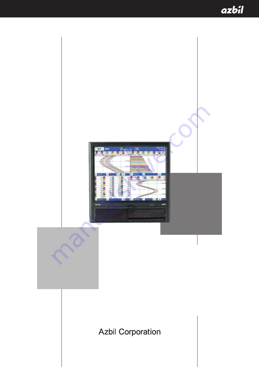
background image

ARF200 

Paperless Recorder

Operation Manual

No. CP-UM-5613E

Thank you for purchasing the ARF200 

Paperless Recorder.
This manual contains information for 

ensuring the correct use of the ARF200 

Paperless Recorder. It also provides neces-

sary information for installation, mainte-

nance, and troubleshooting.
This manual should be read by those who 

design and maintain equipment that uses 

the ARF200 Paperless Recorder. Be sure 

to keep this manual nearby for handy 

reference.

Summary of Contents for ARF200

Page 1: ...ns information for ensuring the correct use of the ARF200 Paperless Recorder It also provides neces sary information for installation mainte nance and troubleshooting This manual should be read by tho...

Page 2: ...anual are subject to change without notice Considerable effort has been made to ensure that this manual is free from inaccuracies and omissions If you should find an error or omission please contact t...

Page 3: ...ury to the operator and others and to prevent damage to property Be sure to observe these safety precautions WARNING Warnings are indicated when mishandling this product might result in death or serio...

Page 4: ...his manual using the specified type of power leads and installation methods Failure to do so might cause electric shock fire or faulty operation Do not disassemble the recorder or touch components ins...

Page 5: ...prevent damage or loss of parts If there is some problem with your order please contact your dealer immediately Name Model No Q ty Remarks ARF200 1 Mounting bracket 1 Wrench 1 CF Card ARF910CF0128 128...

Page 6: ...ounting 5 Panel cutout dimensions 5 Mounting methods 6 3 3 Wiring Precautions 7 3 4 Terminal Block 8 3 5 Wiring of Power and Protective Ground Terminals 9 3 6 Wiring of Measurement Input Terminals 10...

Page 7: ...Screen 43 7 10 CF Card USB Memory Screen 45 7 11 Marker Screen 46 Chapter 8 INITIAL SETTINGS 47 Chapter 9 MENU STRUCTURE 51 Chapter 10 HOME SCREEN 10 1 Quick Recorder Setup 52 10 2 Specifications Dis...

Page 8: ...tions 117 14 5 Zero and Span Adjustment 120 Chapter 15 PART REPLACEMENT 15 1 Replacement Intervals 124 Chapter 16 TROUBLESHOOTING 125 Chapter 17 DISPOSAL 127 Chapter 18 SPECIFICATIONS General specific...

Page 9: ...ned to key combinations for easy writing Annotations can be written on stored and replayed trend screens too Adding a symbol only without text is also possible Various memory functions Start stop of d...

Page 10: ...y open contacts 4 12 relay outputs normally closed contacts 5 12 relay outputs normally open contacts 6 relay outputs normally closed contacts A 8 non voltage contact inputs B 8 non voltage contact in...

Page 11: ...256 256 MB CompactFlash card ARF910CF0512 512 MB CompactFlash card ARF910CF1000 1 GB CompactFlash card ARF910CF2000 2 GB PC card adapter ARF910ADP000 Resistor 81401325 250 0 02 qty 1 Resistor 81446642...

Page 12: ...h options attached Key cover for the functions of keys see chapter 5 Display Mounting bracket 2 left right Rear terminals Power and protective ground terminals Non voltage contact input terminals Meas...

Page 13: ...ration and shock Far from the sources of electrical or magnetic fields Not near flammable liquid or gas Protected from direct sunlight Where terminals are not near a heat source to maximize measuremen...

Page 14: ...screws with the provided wrench or Phillips screwdriver Note that the left and right mounting brackets are different Installation should be done by two people Handling Precautions The recommended tig...

Page 15: ...I O wires 50 cm or more apart For thermocouple TC inputs keep the input terminals away from a heat source a heating body to reduce a reference junction compensation error Don t expose the input termin...

Page 16: ...Alarm relay outputs 12 normally open contacts CH1 12 Power terminals Ethernet connector Protective ground terminals TC mV RTD A terminals TC mV RTD B terminals RTD B terminals CH13 24 CH25 36 CH37 48...

Page 17: ...e Ground Terminals 1 Power and protective ground terminals 100 240VAC 50 60Hz 65VA MAX Power terminals L N Protective ground terminal 2 Connection of power terminals For connection to the power termin...

Page 18: ...the following conditions Settheburnouttodisabled Groundthedevicethatyouwishtoconnectinparallelatonepoint Inaddition installthedeviceneartheARF200andifpossible usethesamepowersupply Donotshutoffthepow...

Page 19: ...12 in each input terminal block and on the ARF _ _ _ AL 1 s input cycle models the C terminals are short circuited between all channels in each input terminal block 11...

Page 20: ...m relay outputs 12 MOS alarm relay output 1a Alarm relay output 1a Alarm relay output 1c COMterminals M3 5 N O rminals M3 5 Digital inputs 8 te Digital inputs 8 From left DI1 DI2 DI8 Digital input DI...

Page 21: ...orm A contact output Example of mechanical relay Form C contact output Power Load b a Buffer relay ARF200 N O COM N Power Load b a Buffer relay ARF200 N O COM C Contact point protective surge absorber...

Page 22: ...ot already have one The MOS relay might burn out if a signal exceeding the contact rating is applied even momentarily To prevent malfunction caused by a light load the most effective mounting position...

Page 23: ...se a non voltage contact signal for digital input terminals Use crimp terminals with insulating sleeves on the end of wires connected to the digital input terminals Digital input specifications Voltag...

Page 24: ...ettings 3 Integration reset Resets the cumulative count When the specified digital input terminal is energized the count is reset See 11 6 Totalizer settings 4 Marker Writes annotations Annotations ca...

Page 25: ...onnection use a crossover cable or a hub Crossover cable ARF200 PC With LAN function N to N connections with PCs When connecting to multiple PCs or to an existing LAN use a hub and straight cables bet...

Page 26: ...recording 11 5 File settings screen Preparations for operation Mount theARF200 in a panel and wire it properly Screen switching Chapter 6 Setting The ARF200 is shipped with default settings but be su...

Page 27: ...tions The front panel is made of glass To avoid injuries due to broken glass protect it from impact Key cover Display 12 1 inch TFT color LCD For operation screens see Chapter 7 View with key cover op...

Page 28: ...splays the DISP menu Takes a snapshot when pressed and held Displays the HOME screen Quits the Home screen Displays the MENU screen or returns from MENU screen to previous screen Returns to the previo...

Page 29: ...focus to the desired character and press the ENTER key The selected character is then displayed in the character input space Character input space When selected uppercase letters symbols and numerals...

Page 30: ...button Displays the operation menu Disk icon Touching this icon starts stops recording Alarm icon Touching this icon when an alarm is generated acknowledges the alarm See 7 2 Hist button Displays hist...

Page 31: ...the screen to the CF card SNAPSHOT folder Pause Stops screen refreshing except for the status bar Press any key to resume During a pause compilation recording and all other processing except drawing...

Page 32: ...se in atmospheres subject to water organic solvents and acid or where the touch panel may come into contact these liquids Avoid use in locations exposed to direct sunlight Wipe off dirt from the touch...

Page 33: ...t that was saved can be read again into internal memory CD card and USB memory See 7 10 CF Card USB Memory Screen Delete operation If is touched while writing on the touch screen the previously drawn...

Page 34: ...een input However since the number of points is sampled periodically writing slowly with the pen will result in more points being used and alternatively writing quickly will result in fewer points bei...

Page 35: ...scroll bar can be made to move automatically by swiping the screen as if to move it to see the latest part of the graph In response to this the trend screen moves automatically and automatic scrolling...

Page 36: ...uch the DISP button of the frame to be expanded and select 1 screen Click the DISP key to set to the frame selection mode click the direction key to select the frame to expand and click the ENTER key...

Page 37: ...terval Chapter 6 SWITCHING SCREENS When the power is turned on initialization takes about 10 to 30 seconds and then an operation screen is displayed With the factory settings the operation screen that...

Page 38: ...tings cannot be changed on the Home screen while recording is in progress Also changing the recording cycle is possible for group 1 only MENU screen Configuration is done mainly on the MENU screen All...

Page 39: ...display Selects the operation screen type Select group Selects a group for display Auto switching Enables or disables automatic switching between groups and channels Switching is enabled when checked...

Page 40: ...een On many screens displays a menu Menu contents differ depending on the screen With touch operation Back button in the settings screen Returns to the previous screen except when the present screen i...

Page 41: ...ys switch the displayed group and the left and right keys switch the displayed channels When trends are displayed horizontally the left and right keys switch the displayed group and the up and down ke...

Page 42: ...below the measurable lower limit lower limit 5 of range was input Or the calculated result falls below the smallest value that can be indicated CAL ER Calculation error The equation is not correct Or...

Page 43: ...color of the status bar is gray for periods other than the scheduled period Group name etc is displayed at the bar below AUTO display is not available See 5 4 1 Currently selected screen type Disk ic...

Page 44: ...not remove the CF card Doing so might damage or destroy the data Before removing the CF card make sure that the round mark is gray Color State Gray The CF card is not being accessed Yellow Data will...

Page 45: ...SP menu are available Special functions of keys see 7 1 above for other functions With touch operation Hist button Displays the historical trend or dual trend screen The same can be done by selecting...

Page 46: ...other functions None 7 5 Numeric Display Screen Data readings for each channel and alarm status are displayed Depending on the number of numeric data display frames and the number of registered group...

Page 47: ...group and the up and down keys switch the displayed channels Pressing this key activates scroll mode which is indicated by a yellow frame around the indicator line on the scroll bar In scroll mode th...

Page 48: ...he data format set for the displayed file is maximum minimum the numeric value display or bar graphs show maximum and minimum values The status bar will indicate either H high or max or L low or min O...

Page 49: ...Special functions of keys see 7 1 above for other functions Same as for historical trends see 7 6 7 8 Alarm Display Screen Alarms that have occurred are listed Activation alarm occurrence date and tim...

Page 50: ...ve for other functions Up and down arrows move the yellow highlighting up and down Left and right arrows are not used With touch operation operate the scroll bar Operation is the same as on the histor...

Page 51: ...oup only are displayed The ENTER menu With touch operation the ENTER menu is displayed by touching a row in the list Trend display The trends recorded in the file of the selected row will appear Speci...

Page 52: ...r of Recordings When 12 Points Are Used 4 byte data 1 3904 83280 2 1920 40960 3 1216 25940 4 896 19110 5 704 15010 6 576 12280 Note If a file is saved in CSV format the numbers of records listed above...

Page 53: ...ber of records Text is displayed in the column The ENTER menu With touch operation the ENTER menu is displayed by touching a row in the list Trend display For binary files the trends recorded in the f...

Page 54: ...the marker for the selected row will be displayed unless the file cannot be found Delete Deletes the marker on the selected row However markers cannot be deleted from a completed file on the CF card D...

Page 55: ...60 Hz Usage group count Clock Input Display File You can exit without changing anything In that case the paperless recorder operates with the default factory settings Press ENTER key when the above me...

Page 56: ...the sub screen Before setting this check the frequency of the power supply you are using 3 Usage group count The sub screen is displayed by touching the button for the Usage group count item The usag...

Page 57: ...button at the Clock settings item For detailed setting instructions refer to 11 11 1 Clock Page 101 5 Input settings The input setting screen below is displayed by touching the Set button at Input se...

Page 58: ...ton at Display settings item For detailed setting instructions refer to 11 3 1 Channel parameters Page 68 7 File settings The file setting screen below is displayed by touching the Set button at File...

Page 59: ...al memory OK cacel settings CopyCF data to USBmemory OK cacel settings Clearing the internal memory data OK cacel settings CS card formatting USB memory formatting OK cacel settings OK cacel settings...

Page 60: ...6 69 200 500 V 2 5 10 20 50 Thermocouple K E J T R S B N W WRe26 WRe5 WRe26 PR40 20 NiMo Ni CR AuFe Platinel 2 U L Resistance thermometer RTD Pt100 JPt100 Pt50 Pt Co Range Set the range The range dep...

Page 61: ...If burnout occurs indication will be upscale DOWN If burnout occurs indication will be downscale Available recording cycle settings Only the ARF _ _ _ AS 100 ms input cycle models can be set to 0 1 0...

Page 62: ...ur distributor after checking the specifications Operation screen Press HOME or Operation MENU settings Home screen HOME Touch or select by and move the focus to Specifications Then press ENTER key Sp...

Page 63: ...y from the operation screen and the MENU screen is displayed Select the desired item with the arrow keys and press ENTER key to switch to the desired parameter setting screen A list of parameters appe...

Page 64: ...ngs and press ENTER key Alarm settings screen Select Alarm settings and press ENTER key File settings screen Select File settings and press ENTER key See 11 4 Alarm settings Page 78 See 11 3 Display s...

Page 65: ...and press ENTER key Schedule settings screen Select Schedule settings and press ENTER key Marker settings screen Select Marker settings and press ENTER key See 11 6 Totalizer settings Page 85 See 11...

Page 66: ...gs screen Select Network settings and press ENTER key System settings screen Select System settings and press ENTER key See 11 10 Network settings Page 91 See 11 9 Memory operations Page 89 See 11 11...

Page 67: ...nels set for calculation No analog inputs are assigned to these channels These channels are for assigning measurement values that use formula By setting up a formula to determine the input value for a...

Page 68: ...120 CH37 128 CH37 120 CH49 128 CH49 120 Digital input channels CH121 128 CH121 128 CH121 128 CH121 128 Touching a channel number displays the detailed setting screen for that channel Note The filter...

Page 69: ...over is reset to the low limit of the scale when it reaches the high limit Range Set the range The range depends on the range type and sensor type Scale Set the scale The scale depends on the range t...

Page 70: ...Units Set the engineering units for the channel Up to 7 one byte characters Usage of formula OFF Raw input data is displayed and recorded for this channel ON Input data processed by a formula is disp...

Page 71: ...can also be done Note X in the table indicates a formula or number Operation Symbol Example Remarks Addition X Y Subtraction X Y Multiplication X Y Division X Y Remainder X Y Exponential X Y Operation...

Page 72: ...previously from the designated channel are used System information acquisition function Symbol Example Remarks Input data CH CH X See the value before the operation of the specified channel 1 Calculat...

Page 73: ...om L min to L s Therefore the ITG is divided by 60 ITG d 60 or ITG d 3600 if the PV unit is L hour If the auto totalizer reset is set to ON the cumulative count will be reset at the totalizer reset ba...

Page 74: ...or the output from an external thermometer and then register the channel as Xh The formula below is used for the dew point temperature t Temperature data h Relative humidity data D Dew point temperatu...

Page 75: ...ing cycle 0 1 s fixed t time constantq x current value of channel X d previous operation results 9 Example of arithmetic expression where calculations are combined CH 1 3 20 6 Channel 1 data 3 20 6 CH...

Page 76: ...nnel can be set Setting the display scale The display scale settings determine how the data is displayed on the screen Item Description Type Standard The upper and lower limit of the display scale can...

Page 77: ...ositioned at the extreme upper right Horizontal direction is shown by When there are multiple channels displayed in the same position the min and max values of the channel with the smallest number are...

Page 78: ...ich the pen is placed For vertical trend graphs For horizontal trend graphs Copying parameters with the copy function The above shows the setup for copying Ch 01 s parameters to Channels 02 to 05 Sele...

Page 79: ...en if 0 is set not to be registered to the group If a channel number is set the registered channel s data will be recorded on the CF card even if the trend display is set to N Set a blank for unused c...

Page 80: ...s of the trip line 11 3 3 Group Parameters 2 Start from the MENU screen Highlight Display settings using the arrow keys Press ENTER key Highlight Common parameters Press ENTER key and the screen shown...

Page 81: ...nes is determined automatically according to the recording interval Time axis ruled line interval Specify the interval between ruled lines on the time axis in trend displays Even numbers from 12 to 51...

Page 82: ...ally increases the size of the data display shown on the trend screen if there are not many registered channels In the following cases data is shown in larger characters Data display Trend direction N...

Page 83: ...one of With or Without When With is selected the minimum and maximum values of that channel data are displayed in the numeric display screen Note however that these values are not displayed when the...

Page 84: ...t ON for Zone usage From the MENU screen when Display settings and then Channel parameters is selected the following screen with an added column for zone is displayed Channels can be assigned to eithe...

Page 85: ...LCD display will turn off The display off timer for the LCD can be set from 1 to 60 minutes If the setting is 0 the display off timer for the LCD does not operate To cancel the display off and resume...

Page 86: ...r limit alarm Error Error alarm Error refers to the occurrence of BURN OVER UNDER CAL ER or RJ ERR Value This determines the threshold for the alarm Ref CH Sets the reference channel for the different...

Page 87: ...l alarms set for one alarm output terminal are activated OR Alarms are assigned with the OR condition for activation of an alarm output terminal The relay turns ON when any of the alarms set for one a...

Page 88: ...Occurrence ON When difference in measured values alarm value Differential upper limit alarm occurs When difference in measured values alarm value Differential lower limit alarm occurs U Differential...

Page 89: ...been set in the recorder s group count setting in System settings Other settings Usage group count is displayed here Select the desired number and press the ENTER key A screen with file settings for...

Page 90: ...he file size time period When a file reaches the specified size it is complete and subsequent recorded data is stored in another file When Auto is specified data is recorded up the file size upper lim...

Page 91: ...TOP key is pressed or when the digital input terminal turns OFF Digital input option Recording stops when the STOP key is pressed or when the digital input terminal turns OFF Recording period After re...

Page 92: ...card when it is complete see 7 9 Minutes No setting 1 min 2 min 3 min 5 min 10 min 20 min 30 min 60 min Note Factory setting is 1 minute Setting the directory 16 characters or less x In saving the da...

Page 93: ...specified here If All channels is selected the settings here apply to all channels Selecting Individual allows each channel to have individual settings CH If Individual is selected the settings on th...

Page 94: ...ptional feature The cumulative count can be reset when the assigned digital input terminal is energized Select None if this function is not needed Note This setting is not displayed if the ARF does no...

Page 95: ...ied by other settings are satisfied the recorder does not record outside of the scheduled period Outside the scheduled period the status bar color changes to gray Schedule settings x Select from none...

Page 96: ...ppear Adding annotations with the optional digital input Annotations can be added to the trends by energizing the digital input terminal Digital input standard When the input terminal designated for d...

Page 97: ...o either CF card or USB memory is selected a list of setting files in the SETUP folder in those files is displayed To overwrite an existing file select that file and press the ENTER key To create a ne...

Page 98: ...ttings with the factory settings Writing internal memory to external memory Writes all data in internal memory to external memory CF card or USB memory Writing CF card data to USB memory Writes the da...

Page 99: ...ork administrator to connect the IP address Subnet mask Sets the subnet mask for this recorder Default gateway Used to set the default gateway address if there is a router etc gateway on the network W...

Page 100: ...NS server Start from the MENU screen Press ENTER key and the screen shown below will be displayed Press the button for the item to be set and then move to the input screen DNS ON OFF Enable disable DN...

Page 101: ...possible Login user name Set the user name that the Administrator or General user will use for logging in to the Web server Login password Set the password that the Administrator or General user will...

Page 102: ...logging in to the FTP server PASV mode For transfer in PASV mode set to ON In PASV mode communication is always one way from the client PC to the server Due to firewall restrictions etc some data can...

Page 103: ...ork The directions below tell how to connect using a Web browser Internet Explorer Netscape Opera Note For connection to the FTP server using a Web browser if a user name other than anonymous is set a...

Page 104: ...om etc is specified instead of an IP address be sure to configure the DNS settings 11 10 2 Check base time and check interval Time synchronization is executed at times determined by the formula Check...

Page 105: ...the recipients when the event defined by a maximum of 8 conditions occurs Start from the MENU screen Press the button for the item to be set and then move to the input screen Select Forwarding addres...

Page 106: ...l is sent every time that the specified time interval elapses Starting and ending CH These settings are effective if Alarm activation time is selected as the forwarding condition The recorder sends e...

Page 107: ...cified in selecting the e mail transfer conditions the data of the channel registered in this screen is written to the mail main text and the mail is sent Condition number Select the e mailing conditi...

Page 108: ...ddress Enter the address of the SMTP server Sender address Enter the e mail address for this recorder If this address is not correct some SMTP servers will not accept e mail transmissions Account Ente...

Page 109: ...ime signal or the like to time the pushing of the button Time correction by DI When the specified digital input turns ON if the number of seconds in the time is less than 30 it will round down to 0 If...

Page 110: ...n it is turned on the following message is displayed Restricted items This menu determines what activities are restricted by the key lock Item Description Setting Prevents access to the MENU and HOME...

Page 111: ...is used for the following x To unlock the keys x To log in and display the web page Setting the password Enter the password for the key lock into the New password field For help see 5 3 Character inpu...

Page 112: ...t screen TCP IP port number Not used by the ARF200 series 11 11 5 Graduation adjustment Start from the MENU screen Press the button for the item to be set and then move to the input screen When gradat...

Page 113: ...l be displayed The touch panel is calibrated before shipment from the factory However coordinates sometimes move out of position with the passing of time If this happens calibrate the coordinates of t...

Page 114: ...emory see 7 9 Internal memory Decimal point symbol For the decimal point symbol either period or comma may be used If the decimal point symbol is a comma and the format for saved files is CSV CSV file...

Page 115: ...t of data change exceeds the equivalent of 1 dot on the screen Thus the trend line will not be out of alignment if data fluctuates only within a range equivalent to 1 dot If Direct is selected the tre...

Page 116: ...is displayed Set the login user name and password in the network settings and Web server settings in the MENU settings Recorder display The same screens as seen on the recorder can be displayed on the...

Page 117: ...rrent display is reloaded Click Auto refresh ON to have the screen updated at about 10 second intervals To stop auto refreshing click Auto refresh OFF 12 1 3 Data display The data for the 128 recordin...

Page 118: ...ion compensation internal external Range Min The minimum value for the range Range Max The maximum value for the range Scale Min The minimum value for the scale Scale Max The maximum value for the sca...

Page 119: ...ngs can be changed during recording Available Settings Item for Alarms1 4 Description see too 11 4 Type None upper limit lower limit differential upper lower limit error Value The threshold for the al...

Page 120: ...or each channel Click the Set button after entering each item and the settings will be written to the recorder The settings cannot be changed while recording is in progress Available settings Item Des...

Page 121: ...ked for a particular group its settings cannot be changed until recording is stopped Available settings Item Description Group name Can be up to 16 characters long Recording period The recording cycle...

Page 122: ...each item and the settings will be written to the recorder When a text is entered in the last row No 10 in the figure 10 more rows appear Up to 50 annotations can be registered See 7 3 and 7 6 for wri...

Page 123: ...7 Selecting External Memory The following message is displayed when the USB memory is inserted Yes Copies files from the previous copy onwards No Nothing happens When the USB memory is next inserted f...

Page 124: ...11 2 Input settings 14 2 Conditions Items Reference conditions Ambient temperature 23 2 C Ambient humidity 50 10 Power voltage 100 Vac 1 Power frequency 50 or 60 Hz 0 5 14 3 Preparation 14 3 1 Requir...

Page 125: ...PUT CH5 INPUT CH9 12 are adjusted by adjusting INPUT CH11 2 Resistance temperature detector input Adjustment is done on three input terminals of each input terminal unit INPUT CH2 CH5 and CH11 Connect...

Page 126: ...re at the terminals The recorder compensates for this amount called reference junction compensation The input used for adjustment comes from the reference junction compensator at a standard 0 C In oth...

Page 127: ...below The thermocouple input can only become as small as the amount of thermo electromotive force equivalent to the temperature at the terminals The recorder compensates for this amount called refere...

Page 128: ...on Settings is selected the adjustment screen below is displayed The numbers displayed are the analog to digital counts after adjustment 14 5 2 Adjustment of the DC voltage input range Connect as show...

Page 129: ...ter inputting the zero voltage and then press Go button 5 Adjust the span Example Adjustment of the 2 V range Input a voltage of 2 V with the DC voltage current generator 6 Wait about 5 seconds after...

Page 130: ...on screen for all ranges 8 Repeat steps 1 to 6 if adjustment is needed for other ranges If the channel to be calibrated is kept open it will not be calibrated 14 5 4 Adjustment of thermocouple input r...

Page 131: ...adjustment the calibration screen for all ranges will be displayed 5 Press ESC key and the MENU screen will be displayed Handling Precautions If a mistake is made in the course of adjustment or if som...

Page 132: ...is based on the half life of the backlight s brightness when the display brightness is set at 3 the factory setting Standard conditions are defined below Item Conditions Temperature 20 to 25 C Humidit...

Page 133: ...w the recorder displays alarm message 1 on the screen at power up and at one hour intervals during operation After the message saying that the battery life will soon end the remaining battery life is...

Page 134: ...k will be behind by the amount of time that the power was off When low battery voltage is detected changing the settings may restore them to default values If the power is turned off a few seconds aft...

Page 135: ...it boards in the case by 3 wires Disconnect them from the pane The front pane is connected to circuit board A by 1 cable Disconnect this cable 4 Circuit board A is connected by 3 cables Disconnect the...

Page 136: ...secondary terminals 20 M min at 500 Vdc Betw alarm output mechanical relay and other secondary terminals 20 M min at 500 Vdc Dielectric strength Betw secondary terminals and ground 1 minute at 500 Vac...

Page 137: ...racy ratings for the internal reference junction compensation Input resolution Approx 1 32 000 converted into reference range Burnout Signal disconnection detection for thermocouple and resistance the...

Page 138: ...ay can be enabled or disabled Shows data tag engineering unit alarm activation status Data display on off selectable data tag unit alarm generation status Current alarm output status alarm log channel...

Page 139: ...ypes Upper limit lower limit differential higher limit differential lower limit error Alarm memory Alarm occurrence time cancellation time and type are stored for the latest 200 alarms the total numbe...

Page 140: ...V 0 to 400 C 0 2 FS 1 digit 400 to 1200 C 0 1 FS 1 digit 1 C R 0 to 1760 C 27 6 mV 0 to 400 C 0 2 FS 1 digit 400 to 1760 C 0 1 FS 1 digit 1 C 0 to 1300 C 13 8 mV 0 to 400 C 0 2 FS 1 digit 400 to 1300...

Page 141: ...0 1 C 200 0 to 300 0 C 220 0 1 FS 1 digit 0 1 C JPt100 200 0 to 649 0 C 400 0 1 FS 1 digit 0 1 C Pt50 200 0 to 649 0 C 220 0 1 FS 1 digit 0 1 C Resistance temperature detector RTD Pt Co 4 0 to 374 0 K...

Page 142: ...134 External dimensions Unit mm Option Option...

Page 143: ...ion results tropical treatment was deleted WARNING was added Standards was changed AAS 511A 014 03 June 2015 5 128 End of a book CE marking EMC directive and Low voltage directive were deleted AAS 511...

Page 144: ...documents provided by Azbil Corporation are for your reference purpose only and you are required to check the functions and safety of your Equipment prior to your use 3 Measures to be taken to secure...

Page 145: ...struments sensors such as pressure flow level sensors regulating valves etc will reach the end of their life due to aged deterioration of parts For those parts that will reach the end of their life du...

Page 146: ...09 Specifications are subject to change without notice 1 12 2 Kawana Fujisawa Kanagawa 251 8522 Japan URL http www azbil com 1st edition July 2011 M 6th edition Aug 2017 V...

Reviews: