Axminster AW12BM, User Manual
The Axminster AW12BM User Manual is a comprehensive guide designed to assist users in understanding and operating the AW12BM model effortlessly. This essential manual is available for free download from our website, ensuring convenient access to detailed instructions and insights for an enhanced woodworking experience.
Share
Download


Reviews:
No comments
Related manuals for AW12BM

CALIANO 6.1 cooK
Brand: Landmann Pages: 2

FRYTON 4.1 cooK
Brand: Landmann Pages: 60

241-0976
Brand: Performax Pages: 19

MT071
Brand: Maktec Pages: 24

Deluxe Kamado
Brand: dellonda Pages: 8

XXLARGE
Brand: YAKINIKU Pages: 142

GR-500-A
Brand: Grilla Pages: 16

47352
Brand: Omcan Pages: 20

nsg3902d
Brand: Uniflame Pages: 18

PREMIER 850BI-2
Brand: Jackson Grills Pages: 22

85-3066-4 (G35305)
Brand: Coleman Pages: 19

AD 18,0/3,0 R
Brand: Flex Pages: 248

AMIGO 3i
Brand: Rebel Pages: 64

DL527502
Brand: Skil Pages: 152

KD 960
Brand: Black & Decker Pages: 72
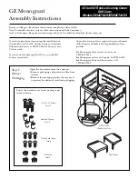
ZX48CTACSS
Brand: GE Pages: 4

ZGG420LCPSS
Brand: GE Pages: 2

ZGG542LCPSS
Brand: GE Pages: 2


