


The following instructions will help you
to connect your DSR switch.
Should you require further assistance, please
consult your installer/user guide.
The Power of Being There
To connect a DSR switch
Quick Installation Guide
DSR
®
Switch
DSR1030 | DSR2030 | DSR4030 | DSR8030 Switches
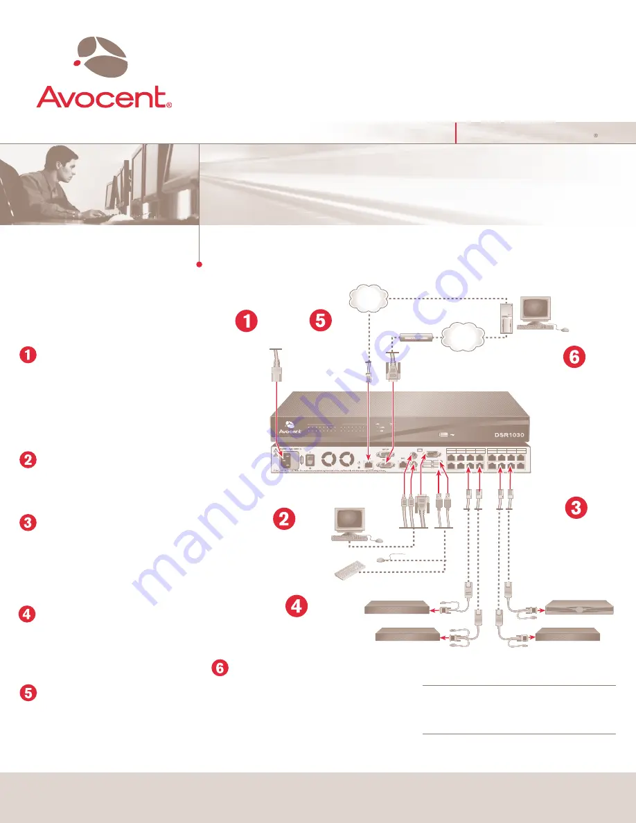
Connecting power to the
DSR switch
Power down all servers that will be part of your DSR
switching system. Locate the power cord that came
with the DSR switch. Plug one end into the power
socket on the rear of the DSR switch. Plug the other
end into an appropriate AC wall outlet.
Connecting the local port
Plug your VGA monitor, PS/2 or USB keyboard and
mouse cables into the appropriately labeled DSR
switch ports.
Connecting a DSRIQ module to
the DSR switch
Choose an available port on the rear of your DSR
switch. Plug one end of a CAT 5 cable (4-pair, up to
10 meters) into a numbered port and plug the other
end into the RJ-45 connector of a DSRIQ module.
Connecting a server to the
DSRIQ module
Plug the DSRIQ module into the appropriate ports on
the back of the server. Repeat this procedure for all
servers that are to be connected to the DSR switch.
Connecting network and
remote users
Plug a CAT 5 cable from your Ethernet network into
the LAN connector on the back of your DSR switch.
Network users will gain access through this port.
Plug in the
keyboard, monitor
and mouse for your
local connection.
Server
Local Connections
Server
Modem
Connect the
switch to the
network.
Connect DSRIQ
modules to the
DSR switch.
Connect servers to
the DSRIQ modules.
Power down all
servers and
attach the
appropriate
power cord to
the DSR switch.
Plug in the
external modem
(optional).
Server
Server
Connecting an external
modem (optional)
The DSR switch may also be accessed using an ITU
V.92, V.90 or V.34-compatible modem. Plug one end of
a 9-pin serial cable into the MODEM connector on the
back of your DSR switch. Plug the other end into the
appropriate connector on the back of the modem.
NOTE:
Using a modem connection instead of a LAN
connection will limit the performance capability of your
DSR switch.
(continued on reverse side)
1
3
5
7
2
4
6
8
9
11
13
10
12
14
15
16
DSR Switch
Check our web site at www.avocent.com/support to search the knowledge base or use the online request.
Avocent, the Avocent logo, The Power of Being There and DSR are registered trademarks of Avocent Corporation. All other marks are the property of their respective owners. © 2005 Avocent Corporation. All rights reserved. 590-473-
6
03A
Telephone
network
Ethernet
Summary of Contents for DSR Series DSR1030
Page 3: ...The Power of Being There 1 3 5 7 2 4 6 8 9 11 13 10 12 14 15 16 ...
Page 4: ...1 3 5 7 2 4 6 8 9 11 13 10 12 14 15 16 The Power of Being There A1 ...
Page 5: ...The Power of Being There 1 3 5 7 2 4 6 8 9 11 13 10 12 14 15 16 ...
Page 6: ...1 3 5 7 2 4 6 8 9 11 13 10 12 14 15 16 The Power of Being There A1 ...
Page 7: ...The Power of Being There 1 3 5 7 2 4 6 8 9 11 13 10 12 14 15 16 ...
Page 8: ...1 3 5 7 2 4 6 8 9 11 13 10 12 14 15 16 The Power of Being There A1 ...


