Quick Installation Guide
Cyclades
®
PM
Intelligent Power Distribution Unit
The Power of Being There
®
Server
Switch
A1
A1
A1
A1
Mounting the PM IPDU (PM8i, PM10 or
PM10i models)
To rack mount or wall mount the PM IPDU,
locate the appropriate sets of holes on the unit.
To rack mount a unit, connect one bracket to
each side of the box using the supplied Phillips
head screws.
Use the mounting hardware recommended for
your rack to mount the PM IPDU. The RJ-45
cable included in the PM IPDU package is
minimum flame rated VW-1 or FT-1 and has a
maximum length of 10 feet (3 meters).
NOTE:
To wall mount a PM IPDU (zero U
model), securely mount it by using a #10 (4.8
mm or 0.19 in or 3/16 in) or larger screw, or use
a drywall fastener rated min. 25 lb (11.34 kg).
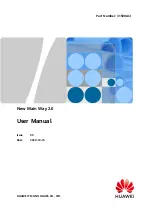
Daisy-chaining PM IPDUs
You can manage a maximum of 128 outlets from
a single workstation by connecting slave PM
IPDUs to the master PM IPDU. Connect one
end of an RJ-45 cable to the Out port of the
main Cyclades PM IPDU, which is connected
to a workstation, a Cyclades console port or
KVM switch AUX port (master). Connect the
other end of the RJ-45 cable to the In port of the
secondary PM IPDU (slave). To attach another
The following instructions will help you
connect your Cyclades PM IPDU.
Should you require further assistance, consult
your installer/administrator/user guide.
To connect the PM IPDU
To Contact Avocent Technical Support CALL (888) 793-8763 VISIT www.avocent.com/support DOWNLOAD www.avocent.com
Avocent, the Avocent logo, The Power of Being There and Cyclades are registered trademarks of Avocent Corporation or its affiliates. All other marks are the property of their respective owners. ©2006 Avocent Corporation. All rights reserved.
590-680-501A
1
PM IPDU to the chain, connect its In port to the last
Out port in the chain. Repeat these steps until you
have connected the desired number of PM IPDUs.
NOTE:
Power the PM IPDU in order to begin
managing power of its connected devices. The
PM IPDU must be powered by a receptacle with
adequate circuit protection
.
2
3
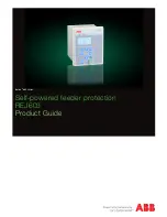
Accessing the console
Connect an RJ-45 cable to the console port on
the PM IPDU. Connect the other end of the RJ-45
cable to an RJ-45 to DB-9F adaptor shipped with
the PM IPDU.
Connect the adaptor to a DB-9 serial port on a
workstation. You may need a USB serial adaptor
in order to connect to the server.
Power Source
PM IPDU
PM IPDU
PM IPDU
PM IPDU