background image

Log cutter/splitter ANNEX 2012 1
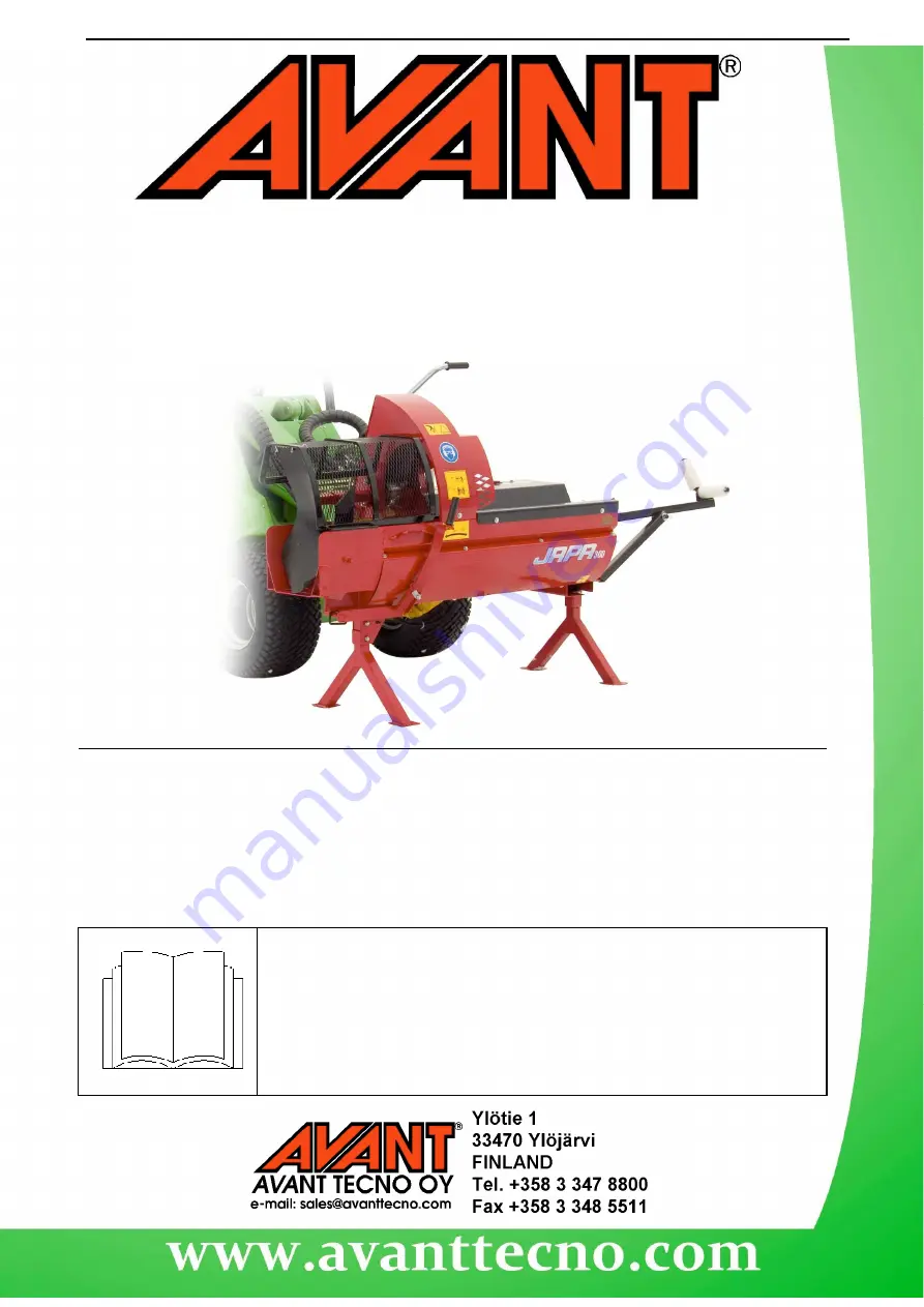
Log Cutter/Splitter

JAPA 300

Product number:

300-700-series loaders:

A21029

200-series loaders:

A21262

Annex

Annex

Annex

Annex

for the original attachment’s

for the original attachment’s

for the original attachment’s

for the original attachment’s

Instruction Manual

Instruction Manual

Instruction Manual

Instruction Manual

Please  read  carefully  the  original  attachment’s  instruction  manual  before
using the equipment, as well as this annex, and follow all instructions.

This annex for the operator’s manual includes specific information about the
use of the equipment with Avant multi purpose loaders.

Keep  the  original  operator’s  manual  as  well  as  this  annex  for  later
reference.

Summary of Contents for A21029

Page 1: ...he original attachment s Instruction Manual Instruction Manual Instruction Manual Instruction Manual Please read carefully the original attachment s instruction manual before using the equipment as well as this annex and follow all instructions This annex for the operator s manual includes specific information about the use of the equipment with Avant multi purpose loaders Keep the original operat...

Page 2: ...cause serious personal injury or property damage Read the warning text accompanying the symbol carefully and ensure that other operators are also familiar with the warnings since personal safety is at stake Note This notice symbol indicates information about the correct operation and maintenance of the equipment Failure to observe the instructions accompanying the symbol can lead to equipment brea...

Page 3: ...s needed for safe operation of the equipment It is not meant to be distributed separately The original instructions manual provided with the machine should be considered as the main source of information about the safety use and the maintenance of the equipment This annex includes important information about the use of the equipment specifically with AVANT multi purpose loaders 2 Designed purpose ...

Page 4: ...keep the centre of gravity low Keep the telescopic boom retracted Keep hands and feet away from moving parts When detaching the log cutter splitter ensure that it is secured against accidental movement Never perform any maintenance or adjustments while the loader engine is running Do not modify the structure of the attachment in a manner that would affect its safety Also read the safety instructio...

Page 5: ...log cutter splitter to the loader Mounting the attachment to the loader is quick and easy but it must be done carefully If the attachment is not locked to the loader it may detach from the loader and cause hazardous situations In the worst case the attachment may fall on the operator or slide onto the driver along a raised boom For this reason the attachment must under no circumstances be raised t...

Page 6: ...can utilise this Step 3 Lift the boom slightly pull the boom control lever backward to raise the attachment off the ground Turn the boom control lever left to turn the bottom section of the quick attach plate onto the attachment Lock the locking pins manually as you connect the hydraulic fittings Before moving or raising the attachment ensure that the locking pins are in the lower position and com...

Page 7: ...nd of the female fitting The hoses should be connected so that the male fitting of the attachment is connected on the loader to the fitting with coloured cap The second hose is connected on the single male fitting of the loader Note that the protective caps on the loader and the attachment can be fastened to each other during operation to reduce the accumulation of dirt In a 200 series machine the...

Page 8: ...stments maintenance or cleaning of the equipment if the splitter can start by accident Shut down the loader engine first 6 1 Setting up the log cutter splitter Transport the log cutter splitter carefully and note the effect of weight at the front to the stability of the loader Choose a level working site which can carry the load of the equipment and the logs The operating area must be even and it ...

Page 9: ...sumes a small amount of hydraulic oil from the loader Check the hydraulic oil level regularly The log splitter is intended to be used by on operator only Never leave the machine unattended with the engine running Do not use the attachment for any other purpose than for cutting and splitting firewood Read the original instruction manual for any further information of adjustments use and maintenance...

Page 10: ......

Page 11: ...TRH Hydraulic driven TR Tractor driven E Electric motor driven BE Gas motor driven ...

Page 12: ......

Page 13: ...s for the conveyor Installation of the splitter cover Operating the machine 39 Notes related to the operation of the machine 40 Service instructions 41 Chainsaws and saw flanges service instructions Gear oil level check and oil change Check and change of the hydraulic oil and the saw lubrication oil Lubrication of bearings Service schedule 44 Warning labels 44 Technical specification 45 Troublesho...

Page 14: ...down carefully the Identification Plate information on the appropriate space reserved on this page so that the info is always easily available when needed Type Japa Firewood Machine 300 E5 6T 300 TR5 6T 300 TRH4T 300 TRH5 6T 300 BE5 6T Serial No Manufacturing year If you are unable to diagnose the fault with the machine contact the machine supplier who will diagnose the problem together with the m...

Page 15: ... dB A Eye protection or safety goggles prevent eye damages caused by flying chips which may otherwise occur in spite of the appropriate guards Non slippery safety boots prevent slipping and protect the operator from foot injuries Non slippery gloves enable tight and firm grip even on a slippery piece of timber Emergency stop The electric motor driven firewood machine is equipped with an emergency ...

Page 16: ...ngine the PTO shaft must be disengaged Before engaging the PTO shaft clutch make sure that there is nobody within the danger zone Always use the correct PTO speed The PTO shaft must be disengaged when not in use U J shaft Before engaging the PTO shaft and during the PTO use make sure that there is nobody within the danger zone Never use anything else except a fault free protected and approved U J ...

Page 17: ...e clamp D9 Remove the belt bracket D10 D11 Lift the conveyor to suitable position and tighten the chain Make sure that the support leg in steady on it s place Maximum angle is 45 degrees D12 Flat belt is tensioned by the upper end hex screws The same screws are used to adjust the belt to run centrally Unloading conveyor into the transport position Perform the above listed operations in the reverse...

Page 18: ...o not saw timber with nails in it Take special care when cutting twisted or long branched trees Ensure that the timber is pressed tight against the cutting table and that it is well supported before commencing sawing Make sure that the timber cannot wedge itself against the blade Do not attempt to cut too long trunks A too long piece of timber will press against the blade The max diameter of a tru...

Page 19: ...s to get it done in a workshop by means of an electric sharpening device pic G3 Filing of the depth regulator depth regulator determines the penetration depth into the wood and thus the thickness of the chip Depth regulation distance becomes smaller along with filing Check the depth regulation distance by means of a reduction diagram If required file with a flat or triangular file The distance bet...

Page 20: ... where bottom is touched and move counterplate so that cylinder stops 10mm before Make a few test runs 1 Left counterplate adjusts how long strike is 2 Right counterplate adjusts how deep the pusher is pulled back 3 Stroke is correct when the pusher end plate is on the same level with the pullback plate G8 5 Adjustment of the splitter valve Adjustment screws 1G7D are the joint swing limiters Adjus...

Page 21: ...lings can only be used once Hose manufacturer does not warrant the hoses for more than five years 9 Storing instructions Clean the machine thoroughly inside and outside Dirt accumulates moisture which causes rust Washing can be done with pressure washer but please avoid directing the water jet straight on the bearing and other parts which can easel be damaged Lubricate all joint with grease Unpain...

Page 22: ...these warnings and instructions are presented in the following illustrations H1 Identification Plate and CE mark H2 Maximum allowed PTO speed H3 Japa stickers H4 Height adjustment of the splitter knife splitting to two parts splitting to four parts H5 U J shaft direction of rotation Arrow on the blade guard indicating the direction of rotation H6 Wear personal ear and eye protection H7 Only one us...

Page 23: ...x limit Max thickness 32 cm Oil pressure has fallen down Check the hydraulic system Oil heats up too much Too little oil cylinder bottoms and oil pressure remains on oil circulates via pressure relief valve Add oil adjusted triggering system and cylinder stroke and swing Check the oil pump Log lifts up when splitting Twisted or knotty log Check the pusher stroke Electric motor does not start Emerg...

Page 24: ...sher pressing force 56 kN Pusher working movement 19 pc min Hydraulic pumps capacity 30 l min Hydraulic oil pressure 200 bar Oil tank capacity 27 l Warranty period 1 year Noise level of the machine Noise pressure equivalent level 89 5 dB A 3 dB Noise effect level 100 5 dB A 1 5 dB Vibration The weight efficiency value of the accelatioeton force by the operator arms m s Product line JAPA 300 E5 6T ...

Page 25: ...1 23 93071 Locking screw M12x40 1 24 506100A Splitter guard 1 25 502017 Tap of cylinder 1 26 506010A Blade guard 1 27 98514 Electric starter 4 kW 380V 1 28 506018A Blade guard shaft 1 29 508100C Saw shaft 1 30 20008003 Saw shaft operating lever 1 31 96095 Chainsaw motor PLM 20 4 S 1 31A 94113 Chainsaw key 1 31B 94139 Chainsaw seal PLM 20 5 1 31C 94136 Support plate to seal 1 31D 94115 Lock ring 1 ...

Page 26: ... controller 1 8 1 62 501056B Support 1 64 506302B Drawbar 1 67 96010 Spring 3 5x16x35 2 68 504011 Leg lug 1 69 504020 Emergency stop only tractor driven 1 70 97129 Rubber of the debris rack 1 71 509602 Fixing iron for the rubber 1 72 507400 Connecting sleeve 1 73 507304 Adjustment piece 1 74 507600 Locking of reversing 1 75 507500 Wobbler 1 76 507700 Safety locking handle 1 77 507302 Intermediate ...

Page 27: ...in for support 6mm 1 10 900912832 Belt 3 2m 6 6m 1 11 9009125A Belt scraper 7 12 9009126A Belt joining pieces 2 13 96151 Bearing UCP 207 2 14 509400AHYD R Lower end roller 1 15 96180 Clutch for shaft Q35 25mm 1 16 50941019 Shaft for motor 1 17 96033 Worm gear 0 18kW 1 18 96074 Hydraulic motor OMP 50 1 19 20009110B Flange for hydraulic motor 1 20 09225 Belt holder 1 21 97131 Lower end rubber 1 22 5...

Page 28: ... repaired and the labour and travel costs of the mechanic are the responsibility of the owner of the machine Possible damages which occur during the transport are not covered by the warranty This warranty expresses and limits our whole responsibility and it replaces and or substitutes all other implied or expressed warranties and responsibilities which otherwise may apply In a case of a request fo...

Page 29: ...5 6T Optional equipment Machine serial Number is in accordance with the machine safety directive 98 37 EEC and the changes made to it enforced by the decree No 1104 99 of the Finnish Government The machine is in accordance with the EU directives applicable and in accordance also with the corresponding national regulations The harmonized standards and proposals for standards as applicable has been ...

Page 30: ... ...

Page 31: ... ...

Page 32: ... ...

Page 33: ... 0 Û ...

Page 34: ... ...

Page 35: ... ...

Page 36: ...0 5 3 0 ...

Page 37: ......

Page 38: ......

Page 39: ......

Page 40: ......

Page 41: ......

Reviews: