background image

Control

Parallel

Profibus DP

Profinet

Modbus RTU

→ 

Modbus TCP/IP

Foundation Fieldbus

HART

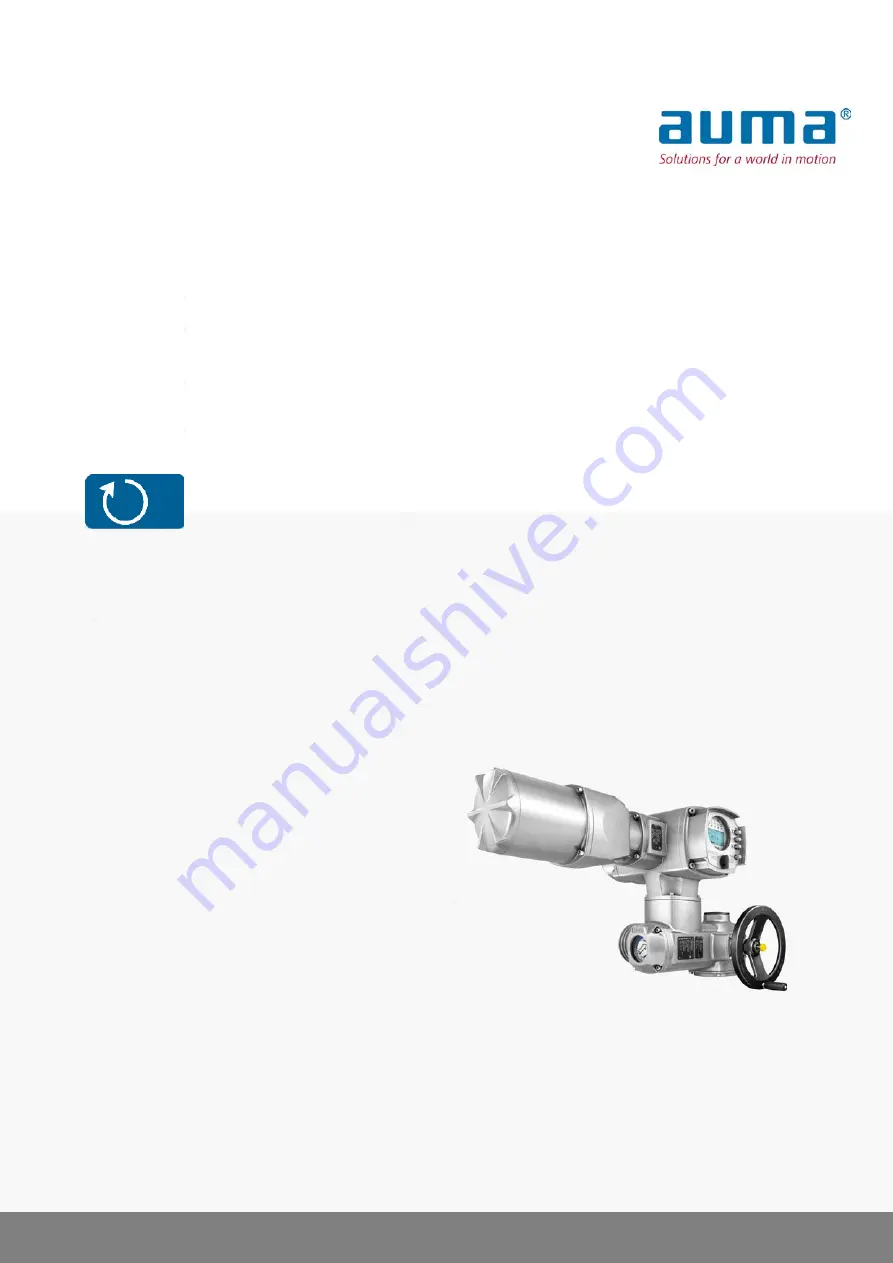
Multi-turn actuators

SAEx 07.2 – SAEx 16.2

SAREx 07.2 – SAREx 16.2

Control unit: electronic (MWG)

with actuator controls

ACExC 01.2 Non-Intrusive

Multiport valve version

Assembly and commissioning

Operation instructions

Summary of Contents for SAEx 07.2

Page 1: ...Modbus TCP IP Foundation Fieldbus HART Multi turn actuators SAEx 07 2 SAEx 16 2 SAREx 07 2 SAREx 16 2 Control unit electronic MWG with actuator controls ACExC 01 2 Non Intrusive Multiport valve version Assembly and commissioning Operation instructions ...

Page 2: ...10 3 Name plate 14 4 Transport and storage 14 4 1 Transport 16 4 2 Storage 17 5 Assembly 17 5 1 Mounting position 17 5 2 Handwheel fitting 17 5 3 Mount actuator to valve 18 5 3 1 Overview of output drive types 18 5 3 2 Output drive type A 19 5 3 2 1 Multi turn actuator with output drive type A mount 21 5 3 2 2 Stem nut for output drive type A finish machining 22 5 3 3 Output drive types B C D and ...

Page 3: ...ontrols 50 9 Signals output signals 50 9 1 Status signals via output contacts digital outputs 50 9 1 1 Assignment of outputs 50 9 1 2 Coding the outputs 50 9 2 Analogue signals analogue outputs 51 10 Commissioning basic settings 51 10 1 Multiport valve 51 10 1 1 Actuator type set check 52 10 1 2 Gear reduction ratio set check 52 10 1 3 Number of ports positions 52 10 1 4 Home port zero position se...

Page 4: ... for servicing and safe operation 70 12 2 Disconnection from the mains 70 12 3 Maintenance 71 12 4 Disposal and recycling 73 13 Technical data 73 13 1 Technical data Multi turn actuators 75 13 2 Technical data Actuator controls 79 13 3 Tightening torques for screws 80 14 Spare parts 80 14 1 Multi turn actuators SAEx 07 2 SAEx 16 2 SAREx 07 2 SAREx 16 2 KES Exd Motor only for V motors incl ref no 8...

Page 5: ...excluded at any time since they will lead to propagating brush discharges and therefore to ignition of a potentially explosive atmosphere This also applies to fireproof coatings or covers available as an option Ignition dangers Gearboxes were subjected to an ignition hazard assessment in compliance with the currently applicable standard according to ISO 80079 36 37 Hot surfaces mechanically genera...

Page 6: ...inuous underwater use observe enclosure protection Potentially explosive areas of zones 0 and 20 Potentially explosive areas of group I mining Radiation exposed areas in nuclear power plants No liability can be assumed for inappropriate or unintended use Observance of these operation instructions is considered as part of the device s designated use These operation instructions are only valid for t...

Page 7: ...rdous situation Failure to observe this warning could result in property damage Is not used for personal injury Safety alert symbol warns of a potential personal injury hazard The signal word here DANGER indicates the level of hazard 1 4 References and symbols The following references and symbols are used in these instructions Information The term Information preceding the text indicates important...

Page 8: ...ying analogue torque feedback signals torque indication and analogue position feedback signals position indication at the actuator controls output In combination with output drive type A the actuator is capable of withstanding thrust Please note Actuators in multiport valve product variant are multi turn and can approach different valve connection Consequently no end stops are available The design...

Page 9: ...ree of charge from our website www auma com AUMA Cloud The AUMA Cloud is the driving element of the digital AUMA world acting as interactive platform for efficient maintenance of AUMA actuators at moderate cost The AUMA Cloud collects all device data of all actuators within one site and provides a clear overview at a glance Detailed analysis provides valuable information on potential maintenance r...

Page 10: ...manufacturer logo CE mark 1 Name of manufacturer 2 Address of manufacturer 3 Type designation 4 Order number 5 Actuator serial number 6 Speed 7 Torque range in direction CLOSE 8 Torque range in direction OPEN 9 Type of lubricant 10 Permissible ambient temperature 11 Can be assigned as an option upon customer request 12 Enclosure protection 13 Data Matrix code 10 SAEx 07 2 SAEx 16 2 SAREx 07 2 SARE...

Page 11: ...rol 11 Data Matrix code Motor name plate Figure 7 Motor name plate example manufacturer logo CE mark 1 Motor type 2 Motor article number 3 Serial number 4 Current type mains voltage 5 Nominal power 6 Nominal current 7 Type of duty 8 Enclosure protection 9 Motor protection temperature protection 10 Insulation class 11 Speed 12 Power factor cos phi 13 Mains frequency 14 Data Matrix code 11 SAEx 07 2...

Page 12: ... 07 2 Flange size F10 Table 2 Description of actuator controls type designation with the example of ACExC 01 2 01 2 ACExC Type AC AUMATIC actuator controls ExC explosion proof version ACExC Size 01 2 01 2 Ex marking Table 3 Marking for explosion protection example of a3b1 1 b 3 a Not used Motor type a ADX or VDX 3 phase AC motor b AEX ACX VEX VCX 1 phase AC motor a Protection type of electrical co...

Page 13: ...s e g A1 B1 The power class defines the max permissible rated power of the motor the switchgear has been designed for The rated power nominal power of the actuator motor is indicated in kW on the motor name plate For the assignment of the AUMA power classes to the nominal power of the motor types refer to the separate electrical data sheets For switchgear without assignment to any power classes th...

Page 14: ...to the actuator Actuators mounted to controls Attach ropes or hooks for the purpose of lifting by hoist only to the actuator and NOT to the controls Respect total weight of combination actuator actuator controls gearbox valve Secure load against falling down sliding or tilting Perform lift trial at low height to eliminate any potential danger e g by tilting Figure 10 Example Lifting the actuator W...

Page 15: ...s heed additional weights 2 Table 8 Weights of multi turn actuators SAEx 07 2 SAEx 14 6 SAREx 07 2 SAREx 14 6 With 1 phase AC motors Weight2 Motor type1 Type designation Actuator approx kg 28 VEX SAEx 07 2 SAREx 07 2 31 AEX 28 VEX SAEx 07 6 SAREx 07 6 31 AEX 40 ACX 32 VEX 48 4 SAEx 10 2 SAREx 10 2 35 VEX 48 2 44 ACX 56 4 47 ACX 56 2 63 VEX SAEx 14 2 SAREx 14 2 65 VCX 67 ACX 67 VEX SAEx 14 6 SAREx ...

Page 16: ...tuator controls may only be stored permanently down to 30 C On request actuators controls may be transported in specific cases and for short duration at temperatures down to 60 C Long term storage For long term storage more than 6 months observe the following points 1 Prior to storage Protect uncoated surfaces in particular the output drive parts and mounting surface with long term corrosion prote...

Page 17: ...ioning Figure 11 Handwheel 1 Spacer 2 Input shaft 3 Handwheel 4 Retaining ring How to proceed 1 If required fit spacer 1 on input shaft 2 2 Slip handwheel 3 onto input shaft 3 Secure handwheel 3 with retaining ring 4 Information The retaining ring 4 together with these operation instructions is stored in a weatherproof bag which is attached to the device prior to delivery 5 3 Mount actuator to val...

Page 18: ...hstanding thrust B B1 B4 C D E 5 3 2 Output drive type A Figure 12 Output drive type A 1 Output mounting flange 2 Stem nut 3 Valve stem Short description Output drive type A consisting of output mounting flange 1 with axial bearing stem nut 2 The stem nut transmits the torque from the actuator hollow shaft to the valve stem 3 Output drive type A can withstand thrusts To adapt the actuators to avai...

Page 19: ...t bore stem nut the stem nut must be finish machined prior to mounting valve stem and prior to performing the following steps page 21 Stem nut for output drive type A finish machining 2 Apply a small quantity of grease to the valve stem 3 Place output drive type A 2 on valve stem and turn until it is 4 flush on the valve flange 4 Turn output drive type A 2 until alignment of the fixing holes 5 Fas...

Page 20: ...orque according to table Table 11 Tightening torques for screws Tightening torque Nm Threads Strength class A2 80 A4 80 24 M8 48 M10 200 M16 392 M20 10 Turn multi turn actuator with handwheel in direction OPEN until valve flange 4 and output drive type A 2 are firmly placed together Figure 16 11 Tighten screws 5 between valve and output drive type A crosswise applying a torque according to table 2...

Page 21: ...2 3 Remove axial bearing washers 2 1 and axial needle roller and cage assemblies 2 2 from stem nut 1 4 Drill and bore stem nut 1 and cut thread 5 Clean the machined stem nut 1 6 Apply sufficient Lithium soap EP multi purpose grease to axial needle roller and cage assemblies 2 2 and axial bearing washers 2 1 ensuring that all hollow spaces are filled with grease 7 Place greased axial needle roller ...

Page 22: ...e type B E Output drive sleeve with bore according to DIN 3210 Output drive types B1 B3 Output drive sleeve with bore according to EN ISO 5210 Output drive types B2 B4 Output drive sleeve with bore according to customer order B4 including special bores like bores without keyway square bore hexagon bore internal splines Output drive type C Output drive sleeve with dog coupling according to EN ISO 5...

Page 23: ... Place multi turn actuator 1 and ensure that the spigot fits uniformly in the recess and that the mounting faces are in complete contact 5 Fasten multi turn actuator with screws according to table Information We recommend applying liquid thread sealing material to the screws to avoid contact corrosion 6 Fasten screws crosswise to a torque according to table Table 12 Tightening torques for screws T...

Page 24: ...r Figure 21 Protection tube made of segments with threaded sleeves 900 mm 2 Segment of stem protection tube 3 V seal 4 Threaded sleeve 3 Push down the sealing ring 3 onto the housing Information For mounting segments push down seals of segments down to the sleeve connecting piece 4 Check whether protective cap 1 for stem protection tube is available in perfect condition and tightly placed on or sc...

Page 25: ...roof enclosure ensure absence of gas and voltage Handle cover and housing parts with care Flameproof joints must neither be damaged nor soiled in any way Do not jam cover during fitting Electrostatic discharge ESD Risk of damage to electronic components Earth both operators and devices 1 Loosen screws and remove the local controls 2 Check whether O ring is in good condition correctly insert O ring...

Page 26: ...red Current type mains voltage mains fre quency Type of current mains voltage and mains frequency must match the data on the actuator controls and motor name plates Also refer to chapter Identification Name plate Figure 23 Motor name plate example 1 Type of current 2 Mains voltage 3 Mains frequency External supply of the electronics For external electronics supply the power supply of actuator cont...

Page 27: ...eating system and external electronics power supply the fuses for the heating system have to be provided by the customer refer to wiring diagram F4 ext Table 15 Fuse for heating system Designation in wiring diagram F4 ext 230 V AC 115 V AC External power supply 1 A T 2 A T Fuse If actuator controls are mounted separately from actuator actuator controls on wall bracket Consider length and cross sec...

Page 28: ...for Industrial Ethernet are to be used Cat 5e for fixed installation 2x2xAWG22 structure Minimum requirement Cat 6e for fixed installation 2x2xAWG22 structure Cable recommendation Prior to installation please note Install network cables at a distance of minimum 20 cm to other cables If possible network cables should be laid in a separate conductive and earthed cable tray Ensure absence of equipote...

Page 29: ...Type of customer connection 2 5 mm 2 flexible 4 mm 2 solid 6 mm 2 10 mm 2 Connection diameter max 6 2 1 Terminal compartment open Figure 25 Terminal compartment open 1 Cover illustration shows type of protection Ex d 2 Screws for cover 3 O ring 4 Blanking plugs 5 Cable gland example 6 Connection frame Electric shock due to presence of hazardous voltage Death or serious injury Disconnect device fro...

Page 30: ...ng torques Tightening torques Terminal cross sections Designation 1 5 1 8 Nm max 10 mm flexible or solid Power contacts U V W 3 0 4 0 Nm max 10 mm flexible or solid PE connection 0 6 0 8 Nm max 2 5 mm flexible or max 4 mm solid Control contacts 1 to 50 1 Remove cable sheathing and insert the wires into the cable glands 2 Fasten cable glands with the specified torque to ensure required enclosure pr...

Page 31: ...onnection 6 2 3 Industrial Ethernet cable connect Information This description applies to the connection via CAT 6A Ethernet cables Figure 28 TCP IP RTU gateway 1 RJ 45 plug in socket for connecting the Industrial Ethernet cable 2 Power supply Cable connection 1 For connecting cables to RJ 45 connectors proceed in compliance with the connector manufacturer specifications When using the RJ 45 conne...

Page 32: ...ring 3 is in good condition replace if damaged 4 Apply a thin film of non acidic grease to the O ring and insert it correctly Flameproof enclosure risk of explosion Risk of death or serious injury Handle cover and housing parts with care Joint surfaces must not be damaged or soiled in any way Do not jam cover during fitting 5 Fit cover 1 and fasten screws 2 evenly crosswise 6 3 External earth conn...

Page 33: ...individual wires with a U bracket cross sections have to be identical 6 4 Accessories for electrical connection 6 4 1 Actuator controls on wall bracket Design Figure 32 Design principle with wall bracket example 1 Wall bracket 2 Connecting cables 3 Electrical connection of wall bracket XM 4 Electrical connection of actuator XA 5 Electrical connection of actuator controls XK customer plug Applicati...

Page 34: ... actuator to the XK customer plug XA XM XK refer to wiring diagram these connecting cables must be subject to an insulation test in compliance with EN 50178 Connecting cables of position transmitters EWG RWG IWG potentiometer do not belong to this group They may not be sub jected to an insulation test 6 4 2 Parking frame Figure 33 PAFEx 01 1 parking frame Application Parking frame for safe storage...

Page 35: ...wheel Table 21 Handwheel marking examples For valve closing turn handwheel in direction of the arrowhead counterclockwise closing clockwise closing Drive shaft valve turns counterclockwise in direction CLOSE Drive shaft valve turns clockwise in direction CLOSE Overload protection for manual operation To protect the valve an overload protection is available as option for manual operation If the tor...

Page 36: ...pe of seating and torque switching 7 2 1 Operating the actuator from local controls Local actuator operation is performed using the local controls push buttons of actuator controls Figure 36 Local controls 1 Push button for operation command in direction OPEN 2 Push button STOP 3 Push button for operation command in direction CLOSE 4 Push button RESET 5 Selector switch 36 SAEx 07 2 SAEx 16 2 SAREx...

Page 37: ...eration when switching on Risk of personal injuries or damage to the valve If the actuator starts unexpectedly Immediately turn selector switch to 0 OFF Check input signals and functions Set selector switch to position Remote control REMOTE Now the actuator can be remote controlled via fieldbus Information For actuators equipped with a positioner it is possible to change over between OPEN CLOSE co...

Page 38: ...up 4 C Cancel process Esc Return to previous display Backlight The display is illuminated in white during normal operation It is illuminated in red in case of a fault The screen illumination is brighter when operating a push button If no push button is operated for 60 seconds the display will become dim again 7 3 1 Menu layout and navigation Groups The indications on the display are divided into 3...

Page 39: ...icates in the bottom row Go to 1 Press push button Go to Display indicates Go to menu M0000 2 Use push buttons Up Down to select figures 0 to 9 3 Press push button Ok to confirm first digit 4 Repeat steps 2 and 3 for all further digits 5 To cancel the process Press C Esc 7 4 User level password User level The user level defines which menu items or parameters can be displayed or modified by the act...

Page 40: ...lay indicates Password 0 3 Use push buttons Up Down to select figures 0 to 9 4 Confirm first digit of password via push button Ok 5 Repeat steps 1 and 2 for all further digits Having confirmed the last digit with Ok access to all parameters within one user level is possible if the password entry is correct 7 4 2 Password change Only the passwords of same or lower access level may be changed Exampl...

Page 41: ...vents unauthorised access by systematic trials The timeout is active for incorrect entries via the local controls as well as incorrect entries via our software tools AUMA CDT AUMA Assistant App After five subsequent incorrect trials further entry is inhibited for one minute Each further incorrect entry doubles the timeout period An active timeout is displayed on the screen An individual timeout is...

Page 42: ...lay indicates Password 0 9 Enter password enter password Display indicates Language and Save bottom row Language selection 10 Select new language via Up Down resulting in the following significations black triangle current setting white triangle selection not saved yet 11 Confirm selection via Save The display changes to the new language The new language selection is saved 42 SAEx 07 2 SAEx 16 2 S...

Page 43: ...igure 44 Self test The language selection menu follows the startup menu Startup menu The current firmware version is displayed during the startup procedure Figure 45 Startup menu with firmware version 05 00 00 xxxx If the language selection feature has been activated during the self test the menu for selecting the display language will now be indicated For further information on language setting p...

Page 44: ...d out after approx 3 seconds Press any push button selector switch in position 0 OFF to fade in the navigation support 8 2 1 Feedback signals from actuator and valve Display indications depend on the actuator version Valve position S0001 S0001 on the display indicates the valve position in of the travel The bar graph display appears after approx 3 seconds When issuing an operation command an arrow...

Page 45: ...point E1 for stepping mode or for intermediate positions with operation profile pivot points and operation behaviour of pivot points The navigation support bottom row is faded out after approx 3 seconds and the axis axes for pivot point display are shown OPEN CLOSE control Active operation commands OPEN CLOSE are shown above the bar graph display The figure below shows the operation command in dir...

Page 46: ...g mode in direction OPEN Stop during operation in direction OPEN Stop during operation in directions OPEN and CLOSE Pause for operation in direction CLOSE Pause for operation in direction OPEN Pause for operation in directions OPEN and CLOSE Multiport valve positions S0017 For activated multiport valve function the display S0017 above the position setpoint E2 indicates a second bar chart showing t...

Page 47: ... seconds Figure 58 Not ready REMOTE indications For further information please also refer to Corrective action Fault S0007 Once a fault has occurred the S0007 display shows the number of faults occurred a blinking exclamation mark after approx 3 seconds Figure 59 Fault For further information please also refer to Corrective action 8 2 3 Status indications according to NAMUR recommendation These in...

Page 48: ...action Maintenance required S0010 The S0010 indication shows maintenance indications according to NAMUR recommendation NE 107 If such an indication has occurred the display shows S0010 the number of indications occurred a blinking square with an oilcan after approx 3 seconds Figure 62 Maintenance required For further information please also refer to Corrective action Failure S0011 The S0011 indica...

Page 49: ...t assignment indications Different indications can be assigned to LEDs 1 5 Device configuration M0053 Local controls M0159 Indication light 1 left M0093 Indication light 2 M0094 Indication light 3 M0095 Indication light 4 M0096 Indicat light 5 right M0097 Signal interm pos M0167 Defaut values Europe Indication light 1 left End p CLOSED blink Indication light 2 Torque fault CLOSE Indication light 3...

Page 50: ...SE Signal DOUT 6 Torque fault OPEN 9 1 2 Coding the outputs The output signals Coding DOUT 1 Coding DOUT 6 can be set either to high active or low active High active output contact closed signal active Low active output contact open signal active Signal active means that the conditions for the signal are fulfilled Required user level Specialist 4 or higher Device configuration M0053 I O interface ...

Page 51: ...ator will either operate the valve at a defined direction of rotation counterclockwise or clockwise or as quickly as possible irrespective of the actuator position to the specified valve port Procedure for commissioning a multiport valve 1 Set check multiport valve parameters generally they are set in the factory prior to delivery Actuator type Gear reduction ratio Number of ports positions Config...

Page 52: ...ts M1141 Default value 8 Setting ranges In operation mode Remote 2 to 10 In operation mode Local or Fieldbus 2 to 16 10 1 4 Home port zero position set The home port is the zero position 0 or 360 of one turn and is consequently the starting point for all other intermediate positions Information Set the gear reduction ratio parameter Reduction ratio M1143 and the actuator type parameter Actuator ty...

Page 53: ...ive Default setting is High active 10 1 5 Positions of valve ports define check Each position can be set to any value between 0 and 360 one full turn of the valve Information Prior to setting the positions the home port must be defined parameter MPV home port This corresponds to the zero position of the valve 0 or 360 of one full valve turn as well as 0 or 100 of position feedback The positions of...

Page 54: ... operated into clockwise or counterclockwise direction display shows CW or CCW Direct operation to a position When selector switch is in position 0 OFF the function Direct operation to a position via push buttons is activated via STEP push button display shows JOG Figure 67 Status indication of multiport valve selector switch in position OFF When changing the selector switch to position Local cont...

Page 55: ... signal e g 24 V DC via Additional inputs or via an additional Parallel interface digital inputs must be provided and configured accordingly Operation to position via digital inputs An input DIN must be configured for each position valve port Configuration of digital inputs Required user level Specialist 4 or higher Device configuration M0053 I O interface M0139 Digital inputs M0116 Example DIN4 i...

Page 56: ...ated by inertia correction Required user level Specialist 4 or higher Customer settings M0041 Multiport valve M1140 Overrun M1656 Default value 0 00 Setting range 0 00 10 0 degrees 10 1 10 Backlash compensation Adjustable backlash compensation of the overall system including valve coupling Required user level Specialist 4 or higher Customer settings M0041 Multiport valve M1140 Backlash comp M1146 ...

Page 57: ...nal behaviour is valid for all positions 10 1 12 Hysteresis for signalling intermediate positions set The hysteresis determines the tripping point Example Parameter Position 4 M1153 is set to 180 50 of the travel Parameter Hysteresis M1148 is set to 3 0 Figure 70 Switching behaviour for signalling behaviours B C D and hysteresis 3 0 P1 Switch on point P2 Switch off point pT Pulse duration 2 times ...

Page 58: ...ld it down for approx 3 seconds Display goes to main menu and indicates Display Select parameter 3 Select parameter either click via the menu to parameter or via direct display press and enter ID M0088 Display indicates Trip torque CLOSE CLOSE or OPEN 4 Use Up Down to select Trip torque CLOSE Trip torque OPEN The black triangle indicates the current selection 5 Press Ok Display shows the set value...

Page 59: ...LOCAL via push button RESET in selector switch position Remote control REMOTE via the fieldbus command reset if the fieldbus is the active command source via a digital input I O interface with RESET command if a digital input is configured for signal RESET and the I O interface is the active command source 10 3 Fieldbus address slave address baud rate parity and monitoring time set Customer settin...

Page 60: ...ube Valve damage due to incorrect direction of rotation If the direction of rotation is wrong switch off immediately press STOP Eliminate cause i e correct phase sequence for cable set wall bracket Repeat test run Check direction of rota tion 1 Move actuator manually to intermediate position or to sufficient distance from end position 2 Depending on the version Unscrew threaded plug 1 with seal 2 ...

Page 61: ...osition OPEN the indication lights go out after travelling into opposite direction The limit switching is set incorrectly if the actuator comes to a standstill before reaching the end position one of the red indication lights LEDs is illuminated torque fault the status indication S0007 in the display signals a fault 3 If the end position setting is incorrect Reset limit switching 61 SAEx 07 2 SAEx...

Page 62: ...ng Instead of the valve position a status text is dis played S0001 For indicated value 0 Press push button Details For details refer to Warnings and Out of specific ation table Collective signal 02 Indicates the number of active warnings S0005 Warnings For indicated value 0 Press push button Details For details refer to Not ready REMOTE and Function check table Collective signal 04 Indicates the n...

Page 63: ...s For an adjusted setpoint range of e g 4 20 mA the input signal is 0 signal loss For a setpoint range of 0 20 mA monitoring is not possible Wrn setpoint position The warning indications are automatically cleared once a new operation command is executed Check valve Check parameterPerm op time manualM0570 The set time parameterPerm op time manu alM0570 has been exceeded The preset operating time is...

Page 64: ...ecting to a 3 phase or 1 phase AC system and with external 24 V DC supply of the electronics One of the phases L1 L2 or L3 is missing Phase fault Correct the sequence of the phase conductors L1 L2 and L3 by exchanging two phases The phase conductors L1 L2 and L3 are connected in the wrong sequence Only applicable if connected to a 3 phase AC sys tem Incorrect phase seq Check mains voltage For 3 ph...

Page 65: ... commands and send one operation command only Set parameter PositionertoFunction active Check setpoint Press push button Details to display a list of de tailed indications For a description of the individual signals refer to Manual Operation and setting Collective signal 13 Possible causes Several operation commands e g OPEN and CLOSE simultaneously or OPEN and SET POINT operation simultaneously A...

Page 66: ... internal 24 V DC supply AUMA art no F3 G fuse according to IEC 60127 2 III 5 x 20 mm Size K006 106 2 0 A T 250 V Voltage output power supply unit 24 V K006 106 2 0 A T 250 V Voltage output power supply unit 115 V F4 Table 34 Secondary fuse F4 internal AC supply 1 AUMA art no F4 G fuse according to IEC 60127 2 III 5 x 20 mm Size K001 184 1 25 A T 250 V Voltage output power supply unit 24 V Voltage...

Page 67: ... of functional failures Carefully assemble power supply unit to avoid pinching the cables 11 3 3 Motor protection thermal monitoring In order to protect against overheating and impermissibly high surface temperatures at the actuator PTC thermistors or thermoswitches are embedded in the motor winding Motor protection trips as soon as the max permissible winding temperature has been reached The actu...

Page 68: ...icing and maintenance The test is performed by simulating the motor protection signal via actuator controls local controls Required user level Specialist 4 or higher Diagnostics M0022 TMS proof test M1950 Test procedure 1 Set selector switch to position 0 OFF 2 Return to the main menu and select the simulation value in parameter TMS proof test M1950 Select Thermal test 3 Activate motor protection ...

Page 69: ... where dust formation represents a potential explosion hazard perform visual inspection for deposit of dirt or dust on a regular basis Clean devices if required Check fastening screws between actuator and gearbox valve for tightness If required fasten screws while applying the tightening torques as indicated in chapter Assembly When rarely operated Perform test run For devices with output drive ty...

Page 70: ...1 and connection frame 4 remain assembled 3 Seal open plug socket connection e g using AUMA protection cover and parking frame Fitting the plug 4 Clean sealing faces of plug socket connector and housing 5 Preserve joint surfaces with an acid free corrosion protection agent 6 Check whether O ring 3 is in good condition replace if damaged 7 Apply a thin film of non acidic grease e g petroleum jelly ...

Page 71: ... originate from breathing due to severe temperature variations e g change of night and day from damaged seals etc Remove any water immedi ately The process temperature range must be within the range of the specified ambi ent temperature Check the flame path gaps of flameproof enclosures for dirt and corrosion Since the dimensions of all flameproof joints are strictly defined and inspected no mecha...

Page 72: ...or controlled waste disposal of the disassembled material or for sep arate recycling according to materials Observe the national regulations for waste disposal 72 SAEx 07 2 SAEx 16 2 SAREx 07 2 SAREx 16 2 Control unit electronic MWG Servicing and maintenance ACExC 01 2 Non Intrusive Modbus TCP IP ...

Page 73: ...th integral starting capacitor and solid state switch CSIR type IM B9 according to IEC 60034 7 IC410 cooling procedure according to IEC 60034 6 Option Refer to motor name plate Permissible variation of mains voltage 10 Permissible variation of mains frequency 5 for 3 phase and 1 phase AC current Mains voltage mains frequency Category III according to IEC 60364 4 443 Overvoltage category F tropical...

Page 74: ...urs Up to 10 operations during immersion Modulating duty is not possible during immersion For exact version refer to actuator controls name plate Pollution degree 4 when closed pollution degree 2 internal Pollution degree according to IEC 60664 1 2 g 10 to 200 Hz AUMA NORM 1 g 10 to 200 Hz for actuators with AMExC or ACExC actuator controls Resistant to vibration during start up or for failures of...

Page 75: ...andard Switchgear Reversing contactors mechanically and electrically interlocked for AUMA power class A3 Options Thyristor unit for mains voltage up to 500 V AC recommended for modulating actuators for AUMA power classes B1 B2 and B3 The reversing contactors are designed for a lifetime of 2 million starts For applications requiring a high number of starts we recommend the use of thyristor units Fo...

Page 76: ...ation CCW green Bluetooth blue Graphic LC display illuminated Standard Local controls Special colours for the indication lights Running indication CW green torque fault CW blue torque fault CCW yellow motor protection tripped violet running indication CCW red Option Bluetooth class II chip version 2 1 With a range up to 10 m in industrial environments supports the SPP Bluetooth profile Serial Port...

Page 77: ...actuator Option AUMA Ex plug socket connector with terminal blocks KES flameproof enclosure Ex d Standard Electrical connection AUMA Ex plug socket connector KT screw type motor terminals push in type control terminals Options Metric threads Standard Threads for cable entries Pg threads NPT threads G threads Options Refer to name plate Wiring diagram Further options for version with MWG in actuato...

Page 78: ...RGENCY operation command enable local controls Interlock CW CCW Process representation output command signals Actual position value Actual torque value requires magnetic limit and torque transmitter MWG in actuator Selector switch in position LOCAL REMOTE Running indication directional Torque switches CW CCW MPV positions Manual operation by handwheel or via local controls Analogue 2 and digital 4...

Page 79: ... Option Accessories For actuator controls mounted separately from the actuator including plug socket connector Connecting cable on request Recommended for high ambient temperatures difficult access or in case of heavy vibration during service Cable length between actuator and actuator controls is max 100 m An MWG is required for position feedback Wall bracket AUMA CDT Commissioning and Diagnostic ...

Page 80: ...i turn actuators SAEx 07 2 SAEx 16 2 SAREx 07 2 SAREx 16 2 KES Exd Motor only for V motors incl ref no 80 SAEx 07 2 SAEx 16 2 SAREx 07 2 SAREx 16 2 Control unit electronic MWG Spare parts ACExC 01 2 Non Intrusive Modbus TCP IP ...

Page 81: ...81 SAEx 07 2 SAEx 16 2 SAREx 07 2 SAREx 16 2 Control unit electronic MWG ACExC 01 2 Non Intrusive Modbus TCP IP Spare parts ...

Page 82: ... 560 2 1 Sub assembly Locking plate 025 0 Switch case for direction CLOSE 560 2 2 Sub assembly Wire for protective earth 058 0 Sub assembly Position transmitter RWG 566 0 Sub assembly 079 0 070 0 Sub assembly Potentiometer for RWG without slip clutch 566 1 Sub assembly Planetary gearing for motor drive only for V motors 079 0 Sub assembly Position transmitter board for RWG 566 2 Sub assembly Reduc...

Page 83: ...14 2 ACExC 01 2 actuator controls with KES electrical connection 83 SAEx 07 2 SAEx 16 2 SAREx 07 2 SAREx 16 2 Control unit electronic MWG ACExC 01 2 Non Intrusive Modbus TCP IP Spare parts ...

Page 84: ...bly Fieldbus board 008 1 Sub assembly Logic board 009 0 Sub assembly Relay board 011 1 Option board 012 0 Sub assembly Cover 500 0 Pin carrier without pins 502 0 Pin for controls 505 0 Sub assembly Pin for motor 506 0 Sub assembly Switchgear 508 0 Padlock 509 1 Sub assembly Fuse kit 510 0 Sub assembly Terminal frame without terminals 528 0 Sub assembly Line bushing actuator connection 532 0 Snap r...

Page 85: ...tion 60 Directives 5 Display indications 43 Disposal 71 E Earth connection 32 Electrical connection 26 EMC 28 Enclosure protection 10 11 11 74 79 Error indication on display 44 Ex certificate 12 Explosion protection 12 Explosion protection marking 12 F Failure indication on display 48 Fault 62 Fault indication on display 47 Fieldbus address 59 Flange size 12 12 Frequency range 26 Function check in...

Page 86: ...ation indica tion on display 47 Output contacts 50 Output drive type A 18 Output drive types 18 Output drive types B 22 Output signals 50 Output signals Potential 27 Overload protection 35 P Parity 59 Parking frame 34 Password 39 Password change 40 Password entry 40 Pollution degree 79 Positioner indication on dis play 45 Positions indication on dis play 46 Position transmitter 13 Power class 11 P...

Page 87: ... 16 Supply networks 26 Support 69 T Technical data 73 Temperature protection 11 Terminal plan 26 Test certificate 12 Test run 60 Timeout 41 Torque indication on display 44 Torque range 10 Torque switching 58 Transport 14 Type 12 Type designation 10 11 Type of current 11 Type of duty 11 73 Type of lubricant 10 Type of networks 26 U User level 39 V Valve attachment 18 73 Valve position indication on...

Page 88: ...ter GmbH Co KG P O Box 1362 DE 79373 Muellheim Tel 49 7631 809 0 Fax 49 7631 809 1250 info auma com www auma com Y009 610 003 en 1 22 For detailed information on AUMA products refer to the Internet www auma com ...

Reviews: