


11/2009
1NO 0027FR-01
1NO0035UK-05 Revision 10/2019
Lieu-Dit Bacqué, rue André Thévet
47400 FAUILLET - FRANCE
Phone: 33 (0)5 53 79 83 20
Fax: 33 (0)5 53 79 96 90
Email: [email protected]
www.atnplatforms.com
www.atnplatforms.com
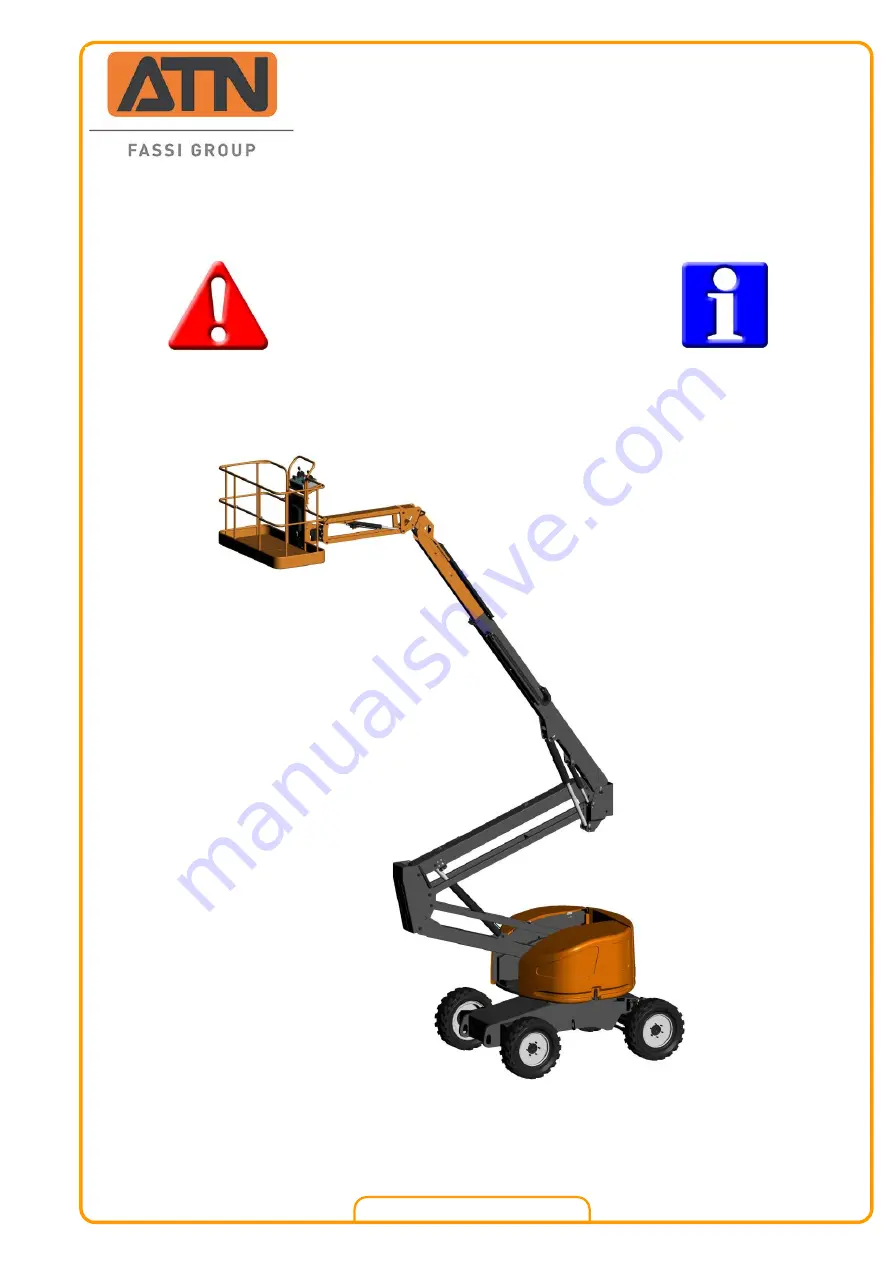
Operator
and
Safety Manual
Zebra 16
Translation of the original manual
Summary of Contents for Zebra 16
Page 2: ...OPERATOR AND SAFETY MANUAL 2 1NO0035UK 05 Zebra 16 DISTRIBUTOR S STAMP...
Page 22: ...OPERATOR AND SAFETY MANUAL 22 1NO0035UK 05 Zebra 16 11 11 11 11 12 12 12 12 8 9 10...
Page 74: ...OPERATOR AND SAFETY MANUAL 74 1NO0035UK 05 Zebra 16...
Page 75: ...OPERATOR AND SAFETY MANUAL 1NO0035UK 05 Zebra 16 75...
Page 76: ...OPERATOR AND SAFETY MANUAL 76 1NO0035UK 05 Zebra 16...
Page 77: ...OPERATOR AND SAFETY MANUAL 1NO0035UK 05 Zebra 16 77 9 2 HYDRAULIC DIAGRAM...
Page 78: ...OPERATOR AND SAFETY MANUAL 78 1NO0035UK 05 Zebra 16...
Page 79: ...OPERATOR AND SAFETY MANUAL 1NO0035UK 05 Zebra 16 79 NOTES...
Page 80: ...OPERATOR AND SAFETY MANUAL 80 1NO0035UK 05 Zebra 16 NOTES...


