


2, rue Pont de Garonne - BP 36
47400 TONNEINS - FRANCE
Tél: 33 (0)5 53 79 80 60
Fax: 33 (0)5 53 79 96 90
Email: [email protected]
www.atnplatforms.com
1NO0024UK-09 révision 11/2013
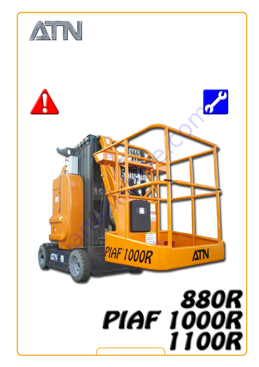
Safety and Maintenance
Manual
Tradu cti on de l a notice
ori ginal e
Transl ation of th e ori ginal
manu al
Summary of Contents for PIAF 1000R
Page 2: ...SAFETY AND MAINTENANCE MANUAL 1NO0024UK 09 2 DISTRIBUTOR STAMP...
Page 8: ...SAFETY AND MAINTENANCE MANUAL 1NO0024UK 09 8...
Page 11: ...SAFETY AND MAINTENANCE MANUAL 1NO0024UK 09 11 Chapter I USE AND SAFETY...
Page 12: ...SAFETY AND MAINTENANCE MANUAL 1NO0024UK 09 12...
Page 16: ...SAFETY AND MAINTENANCE MANUAL 1NO0024UK 09 16...
Page 22: ...SAFETY AND MAINTENANCE MANUAL 1NO0024UK 09 22...
Page 34: ...SAFETY AND MAINTENANCE MANUAL 1NO0024UK 09 34...
Page 36: ...SAFETY AND MAINTENANCE MANUAL 1NO0024UK 09 36...
Page 37: ...SAFETY AND MAINTENANCE MANUAL 1NO0024UK 09 37 Chapter II MAINTENANCE...
Page 38: ...SAFETY AND MAINTENANCE MANUAL 1NO0024UK 09 38...
Page 77: ...SAFETY AND MAINTENANCE MANUAL 1NO0024UK 09 77 3 13 ELECTRICAL DIAGRAM Diagram ref 1EL0023 01...
Page 78: ...SAFETY AND MAINTENANCE MANUAL 1NO0024UK 09 78 NOTES...


