background image

Getting Started 

Requirement 

• 1 x USB Type-C® cable with data transfer function (to connect your PC to the board’s data port) 
• 1 x 12~19V power supply* 
• 1 x Monitor with HDMI cable 
• 1 x Keyboard and Mouse set 
* The power supply is purchased separately. 
* The factory settings only includes a U-Boot bootloader and does not include a system 
 
Before you begin the flashing procedure, please ensure of the following: 
• The board is completely powered off, and the power cord and cables connecting the board to 
your computer are all disconnected. 
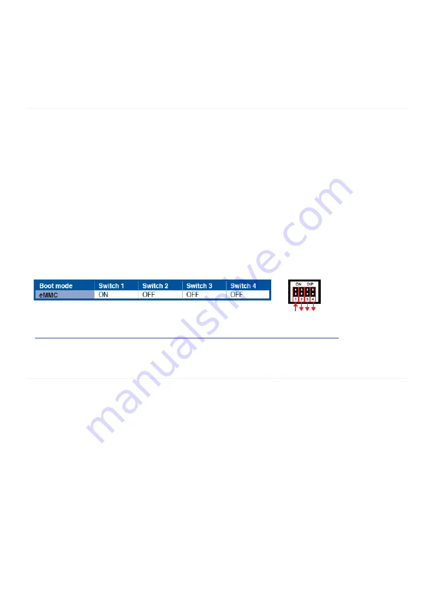
• The boot mode switches are set to eMMC mode, please refer to the table and illustration below 
for the eMMC mode setting.


Image list 

https://www.asus.com/AIoT-Industrial-Solutions/Tinker-Edge-T/HelpDesk_Download/


Flashing the Tinker Edge T 

Initiating Fastboot mode: 

I.


Connect the USB Type-C® cable to the USB Type-C® ports on the Tinker Edge T and your host 
computer. 

II.


Power on the board, you should automatically be booted into Fastboot mode. 


Please note that you will only be booted into Fastboot mode when booting up the Tinker 
Edge T for the first time. 


Please refer to the readme file in the unzipped folder for details on other items such as re-
flash or recovery. 

Executing the flash script: 

I.


Download the OS image from the Tinker Edge T website, then unzip the image file. 

II.


Run the flash script or command file to start the flash process. The flash process should 
take a few minutes. Once the flash is completed, the Tinker Edge T will reboot and you 
should be booted to the terminal prompt. 

Summary of Contents for Tinker Edge T

Page 1: ... https www asus com AIoT Industrial Solutions Tinker Edge T HelpDesk_Download Flashing the Tinker Edge T Initiating Fastboot mode I Connect the USB Type C cable to the USB Type C ports on the Tinker Edge T and your host computer II Power on the board you should automatically be booted into Fastboot mode Please note that you will only be booted into Fastboot mode when booting up the Tinker Edge T f...

Page 2: ...sudo timedatectl set timezone your_time_zone For example to change the system s timezone to Europe Ljubljana you would run sudo timedatectl set timezone Europe Ljubljana o Date Time Enable NTP sudo timedatectl set ntp yes Disable NTP sudo timedatectl set ntp no Set Time need disable NTP sudo timedatectl set time 2016 11 12 sudo timedatectl set time 18 10 40 sudo timedatectl set time 2016 11 12 18 ...

Page 3: ...g command to check detailed connection information Ifconfig eth0 o Wi Fi Select a Wi Fi network by running the following command in the device shell nmtui Then select Activate a connection and select a network from the list under Wi Fi wlan0 Alternatively use the following command to connect to a known network name nmcli dev wifi connect NETWORK_NAME password PASSWORD ifname wlan0 Verify your conn...

Page 4: ...SAI 1 TXC sys class gpio gpio6 GPIO 6 13 14 Ground sys class pwm pwmchip2 pwm0 PWM 4 15 16 GPIO 73 sys class gpio gpio73 3 3V Power 17 18 GPIO 138 sys class gpio gpio138 dev spidev32766 SPI 1 MOSI 19 20 Ground dev spidev32766 SPI 1 MISO 21 22 GPIO 140 sys class gpio gpio140 dev spidev32766 SPI 1 SCLK 23 24 SPI 1 SS0 dev spidev32766 0 Ground 25 26 SPI 1 SS1 dev spidev32766 1 dev i2c 2 I2C 3 SDA 27 ...

Page 5: ...uired by the Edge TPU Python API The Periphery library allows you to select a GPIO or PWM pin with a pin number Other interfaces such as I2C and UART pins must be specified using the pin s device path See the following examples GPIO The following code shows how to instantiate each of the GPIO pins with Periphery gpio6 GPIO 6 in gpio7 GPIO 7 in gpio8 GPIO 8 in gpio138 GPIO 138 in gpio140 GPIO 140 i...

Page 6: ...he following code shows how to instantiate each of the UART ports with Periphery UART1 115200 baud uart1 Serial dev ttymxc0 115200 UART3 9600 baud uart3 Serial dev ttymxc2 9600 Caution UART1 is shared with the Linux serial console To use the UART1 port in your application you must disable the serial console with the following command systemctl stop serial getty ttymxc0 service Note UART3 is not en...

Page 7: ...D_GPIO GPIO 73 out while True try Blink the LED LED_GPIO write True Send HIGH to switch on LED print LED ON time sleep 0 5 LED_GPIO write False Send LOW to switch off LED print LED OFF time sleep 0 5 except KeyboardInterrupt Turn LED off before stopping LED_GPIO write False break except IOError print Error LED_GPIO close Example Run sudo python3 blink py ...

Page 8: ...ure To monitor real time SoC temperature watch n 1 sudo cat sys class thermal thermal_zone0 temp Advanced Script save below text as hwinfo_moniter sh bin bash soc_temp sudo cat sys class thermal thermal_zone0 temp awk printf 2f 0 1000 cpu_freq sudo cat sys devices system cpu cpufreq policy0 cpuinfo_cur_freq awk printf 2f 0 1000000 gpu_freq sudo cat sys kernel debug gc clk grep sh awk printf 2f 4 1...

Page 9: ... sudo chmod x hwinfo_moniter sh hwinfo_moniter sh SoC 55 00 C also can watch it every seconds by watch t p n 1 hwinfo_moniter sh ...

Page 10: ... Requirements 1 Tinker Edge T 2 Image version TINKER_EDGE_T MENDEL 0 0 14 20190904 3 2 x Coral or AIY s MIPI Camera Set up on Tinker Edge T and MIPI Camera 4 Insert the two MIPI camera to the CSI ports Red part of Tinker Edge T Back Front ...

Page 11: ...terminal by mouse Red part 6 Enter the name of demo app in the terminal edgetpu_object_detect or edgetpu_face_detect Red part edgetpu_object_detect Object Detection by MobileNet SSD v2 edgetpu_face_detect Face Detection by MobileNet SSD v2 ...

Page 12: ...imized the terminal by clicking the red part and move the camera windows by hold the windows key mouse left key 8 You should see results like this Congrats You ve just performed an inference on Tinker Edge T ...

Reviews: