ASROCK IMB-380-D, User Manual
The ASROCK IMB-380-D is a cutting-edge motherboard designed for high-performance computing. With a wide range of features and advanced capabilities, this product guarantees an exceptional user experience. Unlock its full potential by accessing the comprehensive User Manual, available for download at manualshive.com – absolutely free of charge.
Share
Download


Reviews:
No comments
Related manuals for IMB-380-D

AVR-H128-CAN
Brand: OLIMEX Pages: 17

TPS65291 EVM
Brand: Texas Instruments Pages: 24

TPA3132D2EVM
Brand: Texas Instruments Pages: 8

MX4LR-GN
Brand: AOpen Pages: 8

ISOFACE ISO2H823V2
Brand: Infineon Pages: 28

EVK-U201SARA
Brand: Ublox Pages: 22

NCP45491PMNGEVB
Brand: ON Semiconductor Pages: 9

GENE-9455 Rev.B
Brand: Aaeon Pages: 64

BOOSTXL-DRV8301
Brand: Texas Instruments Pages: 13

AN3954
Brand: ST Pages: 47

STEVAL-IHM022V1
Brand: ST Pages: 58

HU171
Brand: DFI Pages: 90

G41M-LE
Brand: ASROCK Pages: 1

API Ultimate Performance
UP1100
Brand: Samsung Pages: 2
S3F401F
Brand: Samsung Pages: 32

S3FM02G
Brand: Samsung Pages: 31

SyncMaster 710V
Brand: Samsung Pages: 40
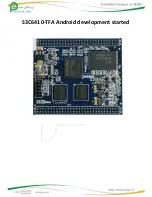
s3c6410-TFA
Brand: Samsung Pages: 49


