

1. Place the IntraSwitch on a flat surface or in an equipment rack.
▲
Important: See “Rack Mounting/Desktop Placement” on the reverse side of
this card for information on securing the switch in an equipment rack or preparing
it for desktop placement.
2. Plug one end of the supplied power cord into the connector on the left side of the
unit’s rear panel.
3. Plug the other
end into a
grounded
AC outlet.
4. Turn on the power
switch (located on the left
side of the unit’s rear panel).
Make sure the front-panel LEDs
blink once and the power light is on.
5. Power off the IntraSwitch.
After the power connection is checked, the switch is ready to be connected to the
network. Proceed to Step 2, “Connect to the Network.”
Quick Installation Guide
IntraSwitch 5324MT
After the IntraSwitch 5324MT is connected to the network and is powered on, you can
configure it for management capabilities, as described in the “Installation” chapter of the
IntraSwitch 5324 User’s Manual.
All other procedures involved in the management and monitoring of the IntraSwitch
5324MT are identical to those for the IntraSwitch 5324 with RJ-45 connectors. Refer to
your IntraSwitch 5324 User’s Manual for details.
1. Make sure the IntraSwitch 5324MT is not powered on.
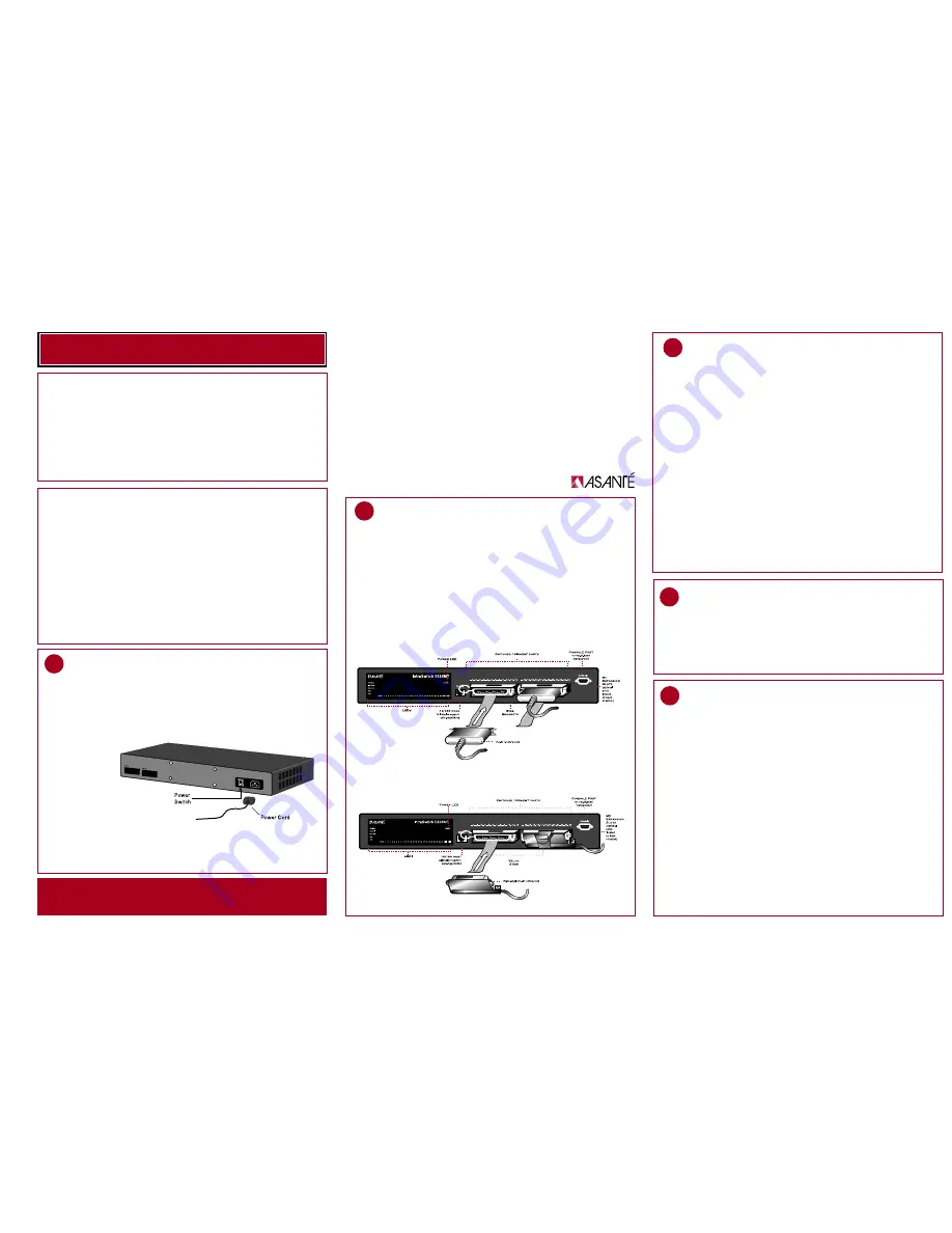
2. Pull the loose ends of the two velcro straps away from the port interfaces on
the front of the IntraSwitch 5324MT.
3. Press each connector into place carefully, making sure you do not bend any of the
connector pins.
4. Depending on whether you a have “T” type connector or a right-angle connector
on your cable, you will need to follow one or the other of the following methods
to secure the connector in place.
Attaching “T” Type Connectors to the 5324MT
If you have “T” type connectors on your cables, screw in the screws provided with them,
or use the wing brackets attached to the 5324MT to secure the connectors, as shown
in the illustration on the top left.
2
Attaching the RJ-21 connectors
1
Plug In and Check Power Connection
Additional materials required:
• Refer to Step #2 (“Connect to the Network”) to determine the cables you need
for connecting the IntraSwitch to the network.
• Phillips screwdriver (#2) for rack-mounting the switch.
Package Contents
The IntraSwitch 5324MT is shipped with the following items:
(1) IntraSwitch 5324MT Ethernet switch
(4) Rubber pads for desktop placement
(1) Power cord
(2) Rack-mounting brackets
(12) Standard Phillips screws for
attaching rack-mounting brackets
Overview
The Asanté IntraSwitch 5324MT is a high-performance, manageable Ethernet switch
that offers 24 10Base-T ports, one 10/100TX port, and two optional Media Independent
Interface (MII) expansion slots. the 5324MT is a special version of the IntraSwitch 5324
designed to accomodate RJ-21 (also known as 50 pin Telco) connectors. In all other
aspects than the connectors, the 5324MT is identical to the IntraSwitch 5324. Refer to
the IntraSwitch 5324 User’s Manual for all procedures and system requirements.
The only difference between the 5324MT and the standard 5324 IntraSwitch is in the
design of the port connections. Instead of having to attach 24 separate push-in RJ-45
connectors, you only need to attach two 50 pin connectors.
(1) CD containing IntraSpection™ Web-
based network management software
(1) IntraSwitch User’s Manual
(1) Quick Installation Guide (this card)
3
Management and Monitoring Capabilities
▲
Skip this step if you plan to use the IntraSwitch as an unmanaged switch.
To use the IntraSwitch 5324MT as a managed switch, it must be configured with
an IP address. This can be accomplished in one of two ways:
• automatically using BootP (default)
• manually via the Console port
BootP Configuration
The IntraSwitch 5324MT is shipped with BootP support. BootP allows the switch to be
automatically configured with an IP address when the switch is connected to the network
and is powered on, if your network contains a BootP server configured with available,
valid IP addresses.
1. Make sure your network has a BootP server configured with a valid IP address
entry for the IntraSwitch 5324MT.
2. When the IntraSwitch is connected to the network and is powered on,
it automatically transmits a BootP request across the network (up to 10 times)
until it receives a valid IP address from the BootP server.
3. After an IP address is received, the switch can be managed via in-band access.
Refer to Chapter 4 of the User’s Manual for more information.
If an IP address is NOT received, the switch will need to be manually configured
with an IP address via the Console port. See “Console Configuration” on back.
3a
Configure for Management
2A
MII ports Cabling Procedures
The two RJ-21 10Base-T ports and one 10/100 port each have an MDI (media dependent
interface), the IEEE 10Base-T standard for unshielded twisted-pair cable) interface.
The 10/100 port and 10 switched put are cabled for straight through connection
to the client workstation.
The optional MII expansion slots allow for the connection of 10/100TX, 100Base-FX,
or 10Base-FL (fiber) ports.
To connect a 10/100TX module to a network station:
• Use a Category 5 UTP cross-over cable with RJ-45 connectors.
To connect a 10/100TX module to a repeater/hub:
• Use a Category 5 UTP straight-through cable with RJ-45 connectors.
To connect a 10/100TX module to a repeater/hub’s uplink port:
• Use a Category 5 UTP cross-over cable with RJ-45 connectors.
To connect a 100Base-FX module to a repeater/hub or to a network station:
• Use a dual 62.5/125 micron graded–index multimode fiber-optic cable fitted
with a dual SC connector.
To connect a 10Base-FL module to a repeater/hub or to a network station:
• Use a dual 62.5/125 micron graded–index multimode fiber-optic cable fitted
with a dual ST connector.
Attaching Right-angle Connectors to the 5324MT
If you have one “T” type and one right-angle connector, attach the “T” connector to
the left socket and the right-angle connector to the right socket.
5. Power on the IntraSwitch 5324MT.


